Hydraloop H300 and H600 have been tested and certified under IAPMO R&T and NSF/ANSI 350 Class R.
SAFETY #
General Safety Instructions #
WARNING
- Before installing or operating any Hydraloop device, carefully review this manual.
- The water produced by a Hydraloop device is non-potable. DO NOT use the output water for drinking purposes. Be aware that the backup water outlet and non-potable outlet are situated closely.
- Only Hydraloop staff, certified Hydraloop partners, or authorized installers should open or service the device to minimize the risk of electric shock.
- Follow the installation manual to ensure the safe and proper installation of the Hydraloop device.
WARNING
- If the power cable is damaged, it should be replaced by Hydraloop staff, a certified Hydraloop partner, or authorized installers.
- Before servicing or conducting maintenance, ensure the Hydraloop device is disconnected from the backup water supply.
ATTENTION
After commissioning or performing any work on the Hydraloop device, it is essential to inspect all water lines thoroughly for leaks and potential cross-connections.
Recommendations #
ATTENTION
- Install the Hydraloop device indoors, maintaining an ambient temperature range of 14-40°C | 57-104°F.
- Avoid exposing the Hydraloop device to direct sunlight.
- Do not connect reusable water to a bidet and/or a toilet hand-shower.
- Ensure the Hydraloop device is always easily accessible for service and maintenance.
ATTENTION
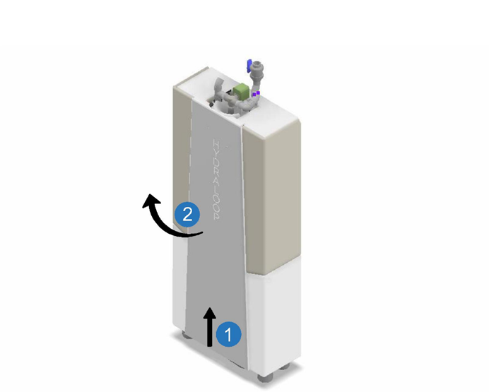
- The Hydraloop device must be moved or transported in an upright, vertical position.
- Be careful to avoid any damage to the exposed underside of the device.
RESPONSIBILITY AND LIABILITY #
Manufacturer #
Hydraloop guarantees the proper working of the device according to its general sales conditions.
As a manufacturer, Hydraloop is not liable in the following cases:
- Failure to follow instructions for Recycle Ready preparation, installation, maintenance, and/or operation of the device
- Inadequate or insufficient maintenance of the device
Installer #
The installer is responsible for the installation and activation of the Hydraloop device:
- Installation shall be according to local legislation, electrical and plumbing codes
- Installer must have obtained login details from Hydraloop Sales Engineer
- Testing and activation via the HDM and all necessary checks
- Maintain commissioning report and record of maintenance within their log
- Explanation of operation as well as the Hydraloop APP to the user/owner
User #
To ensure optimal functioning of the Hydraloop device, please observe the following:
- The Owner Manual
- The assistance of an approved, trained, and qualified installer for Preparation, Installation, Testing, Verification, Activation, and regularly scheduled maintenance of the device
- Regular maintenance is required in which the interval is subject to the quality of the input water
- The operation of the Hydraloop APP
PIPEWORK REQUIREMENTS #
The greywater distribution and collection network shall be carried out in accordance with good plumbing practice as used for water supply and wastewater systems according to EN 806, EN 12056-5 and EN 1610, following the instructions of the manufacturer (see recycle ready guide).
The greywater collection pipework must be:
- Dedicated to greywater
- Sized and laid out in accordance with EN 12056-2, such that the generation of foam is minimized.
- Identified (see recycle ready guide)
- Free draining to avoid stagnation
The greywater collection pipework shall prevent water from other sources entering the greywater system (see recycle ready guide).
Hydraloop systems quantify the water recycled by the systems. I case meters are installed to quantify greywater these must comply with the specifications defined in EN ISO 40064-1 and -5.
The dimensions of Hydraloop devices and the distances and diameters of the connections are specified in the document “Recycle Ready Guide” provided with the system. These dimensions have no tolerances, as the components to which the pipework is connected are rigid parts. To guarantee the correct configuration and dimensions for the connections, the installers are provided with a frame to guide the construction or modification of the greywater collection and recycled water distribution networks.
A sign with a notice of the existence of a non-potable water system shall be installed close to the drinking water mains valve.
The distribution and collection pipework shall be flushed and inspected for watertightness according to EN 806-4 and EN 12056-5 and EN 1610. After installation the system will do a pressure test for cross connections.
RECYCLE READY CHECKLIST #
By now the building has been prepared to be Recycle Ready with the plumbing configuration laid out according to the Hydraloop Recycle Ready document. Please ensure that you have completed and submitted your Recycle Ready Checklist and that you (as the Installer) have prearranged a login for the HDM with a Hydraloop Sales Engineer prior to the installation date (support@hydraloop.com). Without this access activation cannot be performed.
HYDRALOOP H300 SPECIFICATIONS, DIMENSION AND WEIGHTS #
| Hydraloop H300 | |
| Volume | 300 liters | 80 gallons |
| Cleaning capacity | 360 liters | 95 gallons per day depending on user behavior |
| Voltage | 100 / 240V, 24V internal |
| Average power consumption | 220 kWh/year, 25W during treatment |
| WiFi | The Hydraloop device needs to be connected with an internal WiFi-network |
| Sound Level | ± 44 dB. |
| Greywater input sources | – shower – bath – washing machine (with inlet diverter) |
| HYDRALOOP MODEL | HEIGHT (MM) | WIDTH (MM) | LENGTH (MM) | DRY WEIGHT (KG) | WET WEIGHT (KG) |
| H300 | 2045 | 335 | 810 | 82,5 | 383 |
| H300 PACKAGED | 2198 | 345 | 815 | 90,5 | – |
| H300 DISPLAY MODEL | 2045 | 335 | 810 | 40 | – |
| H300 DISPLAY MODEL PACKAGED | 2198 | 345 | 815 | 50 | – |
OFF-LOADING AND UNPACKING INSTRUCTIONS #
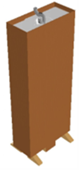
The Hydraloop device will be transported to your location mounted and strapped onto a HL-Transport plate, wrapped in protective packaging, and mounted onto a wooden pallet.
- When moving the Hydraloop device, it is important to always keep it in an upright, vertical position. A horizontal position may cause damage to the devices’ internal components and seals.
- Leave the protective packaging on the device until it is placed at its final installation position.
- Once the device is taken off its wooden pallet, leave it strapped to the wooden transportation plate. It can then be moved with a 2-wheel trolley.
- Only when it is near its final position do you remove the packaging and carefully lift the device from the plate.
*NOTE: Please do not remove the Hydraloop device from transportation plate until it has reached its final location. Do not use any apparatus underneath the device to move it as this will cause damage to the exposed underside.
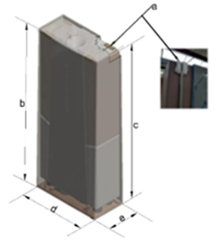
a – edge protection
b – H: with skid: 219cm | 86”
c – H: without skid: 189cm| 74”
d – L: 82 cm| 32”
e – W: 35 cm | 14”
Dry Weight: 92 kg | 203 lbs
Wet Weight: 382 kg | 846 lbs
The H300 comes with the following items:
- H300 Device
- PVC ball valve
- Power cable
- Mesh inline filter
- Flexible connectors (3x)
- Quick Reference Guide
INSTALLATION CONSIDERATIONS #
Basic installation steps:
- Prior to installation ensure that you are following applicable plumbing and electrical guidelines in your city or state/province and that your plumbing configuration is protected against backflow and cross connection maintaining the safety of the public water supply.
- Position the Hydraloop device in its planned location.
- Connect H300 wastewater outlet to sewer.
- Connect incoming greywater to the inlet on the top of the device via inlet manifold, in combination with external lift pump if necessary.
- Connect the backup water supply and open
- Plug 100/240V power cord into wall socket.
- Run the Testing, Verification and Activation using the HDM with your Hydraloop Sales Engineer.
H300 INSTALLATION ORIENTATION #
The H300 device is to be installed against the wall, leaving room for the electrical connection. The device must be secured to the wall to protect against falling over. The top plate comes equipped with two anti-fall straps which are adjustable. Simply adjust the bend plates according to its desired position. Then affix bend plates to the wall.
Inlet Manifold – Anti-Fall Traps
Inlet Manifold W/ Inlet Diverter – Anti-Fall Straps:
FRONT PLATE REMOVAL #
To remove the stainless-steel front plate, use a lever on the lower side of the front plate to carefully lift the stainless plate upwards. The plate is holding its position due to its shape so once it moves upwards it will be free to remove. Disconnect the LED light connection from the front plate and put the plate aside.
| 1 | Carefully wedge a wooden (broom stick handle) or plastic tool between the bottom of the front plate and the floor and move the front plate upwards. |
| 2 | Remove the front plate off the device. Disconnect the earth wire and LED light connection (Premium model) from the top of the front plate being careful not to break the wire connection. *Place the front plate in a way that the front plate cannot fall and be damaged. |
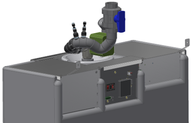
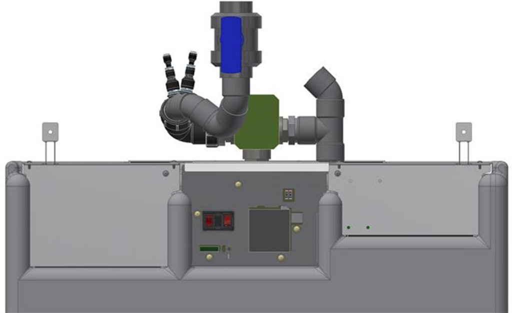
H300 GREYWATER INLET MANIFOLD INSTALLATION: 2 VERSIONS #
The H300 comes standard with the inlet manifold shown below. This will be installed at the factory.
| 1 | Incoming water sensor |
| 2 | Incoming water sensor |
| 3 | Ventilation valve |
| 4 | Foam injection inlet |
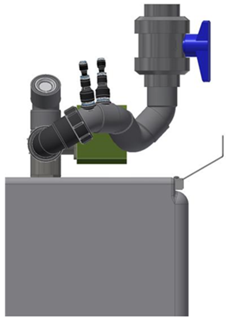
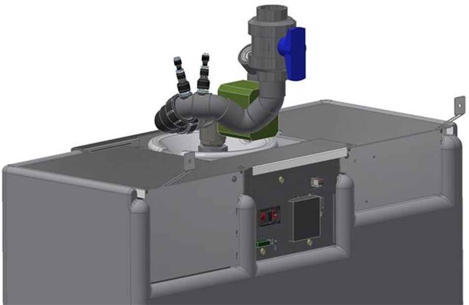
Affix hand valve to inlet manifold: #
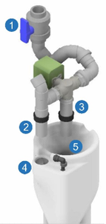
| 1 | 3-way valve |
| 2 | Overflow pipe |
| 3 | T1 tank inflow pipe |
| 4 | T1 Overflow inlet shoulder |
| 5 | T1 Tank inflow |
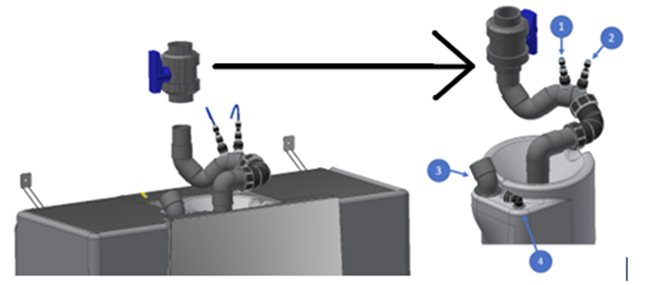
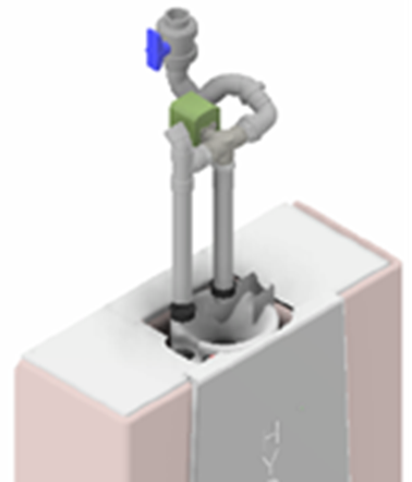
Install H300 inlet manifold with inlet diverter as follows: #
- Take the grey inlet manifold with its two pipes (each with 40 mm | 1 ½” OD) and carefully install the manifold into the top inlet of the T1 tank.
- Stand in front of the device and hold the inlet manifold in front of you, with the electronic 3-way valve head (#1 in the drawing) and the 40mm |1 ½” OD grey water inlet pointing away from you. The 40 mm |1 ½” OD pipe on your left (#2 in the drawing) is the overflow and the centre pipe (#3 in the drawing) is the T1 inflow pipe.
- Lubricant (Vaseline) must be applied to the black rubber ring and the T1 inflow pipe. Place the rubber seal on the overflow pipe, all the way to the T-piece edge. Lubricate the outside and the overflow inlet hole (#4 in the drawing), also situated on your left side of T1 tank.
- Lubricate the second rubber ring, inside and outside, as well as the centre pipe and the T1 inlet port.
- Slide both pipes into their respective holes and press down until the overflow pipe T-piece is resting on the T1 overflow inlet shoulder.
Connect the supplied 40 mm | 1 ½” shut off valve into the Hydraloop inlet manifold and connect the 40 mm | 1 ½” grey water delivery pipe into the shut off valve.
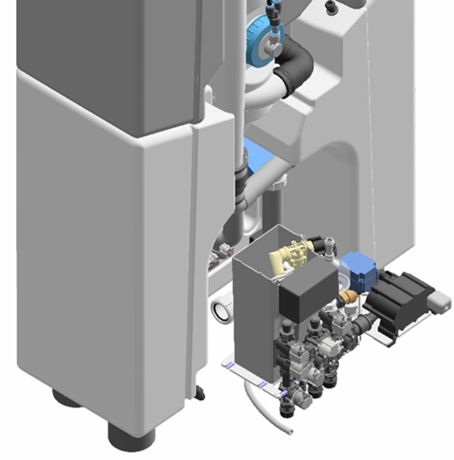
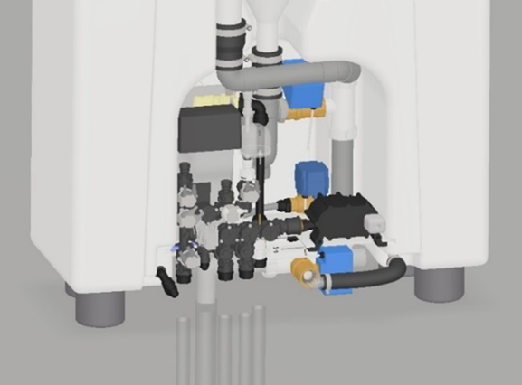
REUSABLE WATER OUTLETS #
The Hydraloop device comes equipped with three standard outlet valves, (1) dedicated for feeding multiple toilets (no high flush toilets) and (1) dedicated for feeding one washing machine and (1) auxiliary outlet (irrigation).
Note that this third valve will not be permanently pressurized, unlike the other two reusable water outlets. This outlet’s standard function is to supply reusable water when a surplus is available.
Note the outlet connections on the H300 in the drawing below:
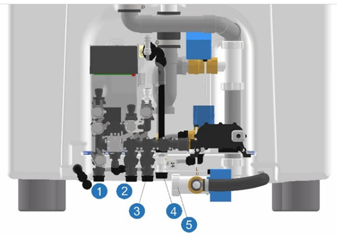
| Connection specifications Hydraloop H300 & H600 | |||||
| Input connection | Size (imperial) | Size (metric) | Thread type | Additional information | |
| Greywater supply | 1 ½” | 40 mm (OD) | PVC | Into feed channel | |
| 4 | Backup water supply | ½” | 15 mm | male | |
| Inlet diverter (optional) | 1 ½” | 40 mm (OD) | PVC | ||
| Output connection | Size (imperial) | Size (metric) | Thread type | Additional information | |
| 2 | Toilet supply | ½” | 15 mm | male | Connect to flexible hose |
| 3 | Washing machine supply | ½” | 15 mm | male | Connect to flexible hose |
| 1 | Auxiliary outlet (optional) | ½” | 15 mm | male | Connect to flexible hose |
| 5 | Wastewater line | 1 ½” | 40 mm (OD) | PVC | *Into rubber sleeve – 40 mm ID or 40/50 adapter |
H300 WASTEWATER OUTLET INSTALLATION #
The 40 mm | 1 1/2″ OD wastewater line at the bottom of the H300 needs to be connected to the sewer with the PVC eccentric adapter ring or *rubber reducing sleeve (40 mm ID or 40/50) through the floor (first image) or backwards into the wall (second image). Please note that the rubber reducing sleeve do not come with the Hydraloop device and must be provided by the installer.

*Rubber reducing sleeve – 40 mm ID or 40/50 rubber adapter: OR equivalent available in your country –
Not included with the Hydraloop device
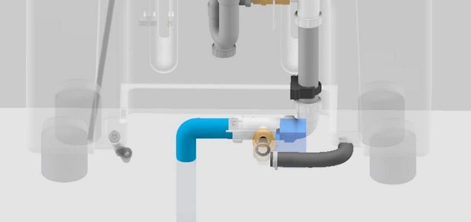
Option 1:
H300 drain line connected to sewer system by using reducing sleeve through the floor.
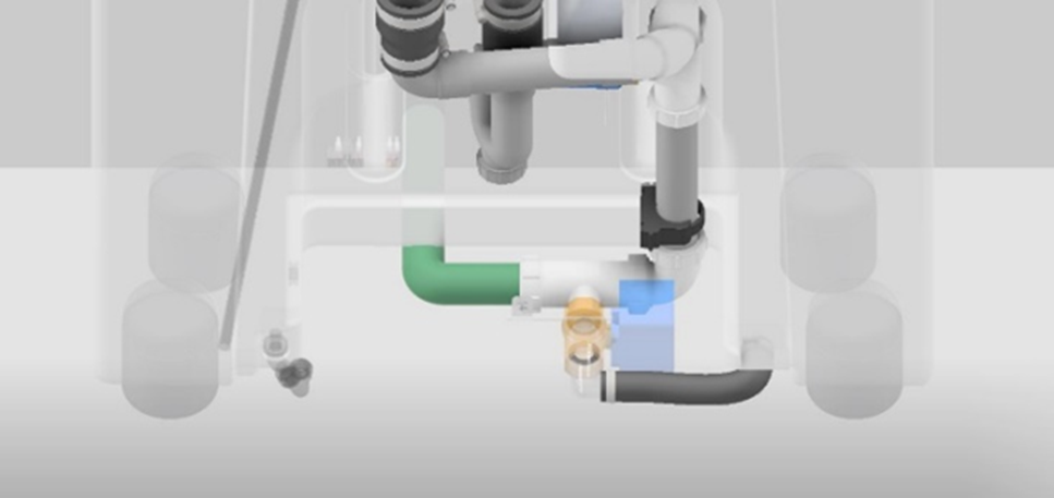
Option 2:
H300 drain line connected to sewer system through the back wall.
INTRODUCING AN EXTERNAL LIFT PUMP #
If the Hydraloop device is on the same or higher floor as the shower/bath or washing machine an external lift pump needs to be incorporated to have the source greywater enter the device.
To discuss alternate options for introducing an external lift pump please refer to your Recycle Ready document or speak to your Hydraloop Sales Engineer for assistance at support@hydraloop.com.
NOTE: When servicing the lift pump please have Hydraloop device on bypass so as not to potentially clog the device with particulate that may have accumulated in the lift pump over time.
INSTALLATION #
The Installation, Verification and Activation of the Hydraloop device should only be carried out by approved installers who have prearranged for their HDM login. This can only be done through messaging support@hydraloop.com. Once you have made your appointment you will receive authorization and your login.
The drawing below is a reference to the piping configuration that has been completed via the Recycle Ready Guide.
RECYCLE READY PLUMBING DIAGRAM #

| 1 | Backup water |
| 2 | Greywater and condensation water |
| 3 | Lift pump |
| 4 | Sewage line |
| 5 | Lift pump overflow + maintenance waste |
| 5 | greywater and condensation water inlet |
| 6 | washing machine greywater lift pump |
| 7 | washing machine reuasable water feed |
| 8 | toilet reusable water feed |
| 9 | auxiliary reusable water feed (garden or pool) |
| 10 | ventilation |
| 11 | manual three-way bypass valve (not included with device) |
| 12 | electrical inlet diverter (for washing machine greywater input) |
PREPARATION, INSTALLATION, TESTING, VERIFICATION AND ACTIVATION OF THE H300 DEVICE #
- Preparation – Recycle Ready configuration and Recycle Ready checklist must be complete and submitted to support@hydraloop.com
- Installation
- Delivering of H300 to site
- Unboxing of the device
- Placing the device in position
- Securing the device to the back wall leaving room for electrical connections
- Connection of greywater inlet, backup water and reusable water lines
- Applying electrical connection
- Testing, Verification and Activation: This step is conducted through the HDM by an approved and trained Installer with a pre-requested login to the HDM. Hydraloop Sales Engineers will be available for first time installers to assist and guide them through the process.
- Switch device from greywater bypass to the Hydraloop device
- Go through testing of all device systems via the HDM “verification”
- Select priority options connected to toilets, washing machine, auxiliary outlet, and lift pumps
- Activation of the H300 when all device systems have passed the validation steps. This will occur automatically once all HDM steps have been completed.
- Commissioning: This step will be conducted through the APP, by the client, or someone assisting the client when the client is occupying the home, and permanent Wi-Fi has been established.
- Set up permanent Wi-Fi connection through the APP. Ethernet connection is also available on the device.
- Connect the client’s smartphone to the Hydraloop device through the APP
- Fill in the Warranty information via the APP. At this point in time the Warranty period will start as well as the start-up time
Activation of the device cannot be performed until installer has registered for an HDM login.
Accessing the HDM: #
- Open hdm.hydraloop.com in your browser
- Sign in with your Username and Password as supplied via email from your Hydraloop Sales Engineer
- Two-factor authentication is required, enable it to gain complete access
- Install the APP of your operating system choice
- Scan QR code
- Enter verification code
- Change your password
- Save Changes (Save icon in top right-hand corner)
Once logged into HDM you will be instructed to scan the barcode on the top of the Hydraloop device. Scanning the barcode will open your device up onto the HDM and the verification process will begin. You will be given instructions on how to proceed to the next steps.
The Hydraloop APP needs to be downloaded on both the Installers and device owners smartphone.
If you need assistance, please call your Hydraloop dealer or contact Hydraloop Sales Engineer via email support@hydraloop.com
STARTUP TIME #
The Hydraloop device requires a minimum of 21 days (3 weeks) and 20 showers to develop the biological treatment process in the T2 tanks and become fully operational. The greywater treatment will start from the initial start-up; however, this reusable water will be purged into the sewer and the backup water will be supplied instead. After this start-up period of 21 days (3 weeks) and 20 showers, the Hydraloop device will automatically switch over to deliver reusable water to the toilets, washing machine and/or auxiliary outlet.
BACKUP WATER & BACKFLOW PREVENTION #
If there is not enough reusable water available, the device will automatically switch to backup water. The device is connected to its backup water supply via an air gap to protect the tap water against backflow or cross contamination. Additionally, a non-return valve is mounted on the point of incoming backup water.
NOTE: If using rainwater as a backup water supply pretreatment must be applied prior to entering the Hydraloop device; this treatment must be done according to EN 16941-1. Pretreatment should include a 5-micron filter and carbon filtration, UV disinfection, expansion vessel and a pressure regulator (depending on the booster pump). The incoming flowrate should not exceed 12 lpm | 3.2 gpm, 1.5-3 bar | 21.75 – 43.5 psi.
PLUMBING BACKUP FACILITY #
During periods of unscheduled maintenance, service, or power failure it might be possible that supply of reusable water backup water is temporarily not available. To overcome this a bypass option can be installed. The bypass setup must comply with the applicable regulations of the country, state, or municipality.
SYSTEM MALFUNCTION #
Your Hydraloop device is very reliable, with all critical components being monitored continuously by the Hydraloop server through your Wi-Fi internet connection. In the unlikely event a component fails – for example the UV lamp – the Hydraloop system will automatically switch to backup water with no reusable water being distributed as a precaution.
Note: Hydraloop Systems BV is not liable for any damage if the above or any other abnormal substances enters the Hydraloop device causing the system and/or the washing machine damage.
Warning #
Hydraloop device is designed for ‘normal usage’ and is not designed to receive solid materials like stones, chemicals, paint residues, hair dye, bleach, disinfectants, or any other matter that is unusual for shower/bath and washing machine greywater. In the event these substances enter the H300, it can be damaged, and the water treatment can be affected. There is a function in the APP where the greywater from the T1 tank can be wasted to the sewer if you suspect foreign matter has entered the Hydraloop device (i.e., hair dye or bleach).
Note: Hydraloop Systems BV is not liable for any damage if the above or any other abnormal substances enter the H300.
EXPLANATION VISUAL ALARM LIGHT AND AUDIBLE ALARM #
VISUAL STATUS INDICATIONS #
White light: A white light indicates that there is a sufficient volume of reusable water for all uses.
Blue light: A blue light indicates that there is currently no reusable water available and backup water is being used for all purposes.
Blue white alternate light: A blue-white alternating light indicates that there is reusable water in the storage tank, but not enough for a full washing machine cycle.
Green light: A green light indicates that the Hydraloop device is in automatic cleaning mode.
Purple light: A purple light indicates that the Hydraloop device is detecting that the washing machine is in operation.
Orange light: An orange light indicates that your Hydraloop device is currently not treating greywater and has automatically switched over to backup water.
Since your device is monitored 24/7, your Hydraloop installer knows about this. If the status light does not change after 24 hours, please contact Hydraloop support in your Hydraloop app.
Red light: A red light on the LED panel can indicate two things.
1. The Hydraloop device detects an issue with your toilets or washing machine.
2. There is an issue with the Hydraloop device, and no water can be distributed to the toilets and washing machines. In the event of a red light, please open your Hydraloop app and contact Hydraloop directly.
AUDIBLE STATUS INDICATIONS #
High water level: Buzzer alarm: 2 beeps every minute, visual alarm: 2 pulses every minute
Air pump: Buzzer alarm: 3 beeps every minute, visual alarm: 3 pulses every minute
UV lamp: Buzzer alarm: 4 beeps every minute, visual alarm: 4 pulses every minute
Water storage tank re-disinfection circulation: Buzzer alarm 5 beeps every minute, visual alarm: 5 pulses every minute
Water distribution pump: Buzzer alarm: 6 beeps every minute, visual alarm: 6 pulses every minute
If you need assistance, please call your Hydraloop installer or contact Hydraloop directly via support@hydraloop.com or the Hydraloop app.
WARRANTY #
For detailed information on the warranty coverage, please review your warranty certificate. It is essential to ensure that all your personal information is accurately entered into your Hydraloop APP.
Under this Factory Warranty (“Warranty”), Hydraloop guarantees to the original purchaser of the Hydraloop device (referred to as the “Product”) as outlined in Part 1 of the Warranty Policy under “Customer,” that the Product will be free from material Defects for a period of two (2) years from the date of the original purchase invoice from Hydraloop or one of its authorized Partners, unless local jurisdiction mandates a longer term. In these warranty terms, a “Defect” refers to a manufacturing or design flaw that significantly affects the Product’s use, solely attributable to Hydraloop, and not detectable at the time of Product delivery.
To assist Hydraloop device owners in entering their information, contact details, and physical address into the warranty section on the Hydraloop APP, the Hydraloop installer will provide support.
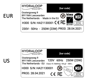
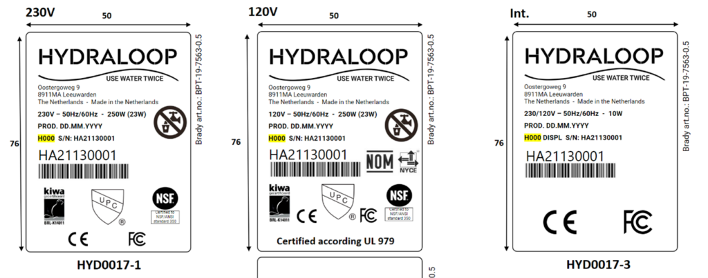
DATA PLATE/ SERVICE LABEL #
The Hydraloop device has a permanent data plate attached to the top of the device that should look like the example below.
This document and its contents are the sole property of Hydraloop Systems B.V. and must not be copied to a third party, either in part or whole, without the prior written consent of Hydraloop Systems B.V.
Hydraloop reserves the right to change the specifications stated in this document.
Hydraloop products are protected by patents and patents pending. The Hydraloop brand name is a registered trademark.
GLOSSARY OF TERMS #
Auxiliary Outlet: This valve allows for the distribution of reusable water to be used for the garden, irrigation, or pool top-up (depending on your region). This outlet is non-pressurized.
Backup water: Water that is used as a main source of water in the building. This could be tap water, municipal water, well water, rain water etc. Another term for backup water is ‘mains water’.
Blackwater: Contaminated wastewater containing pathogens from human waste and other organic materials. This waste stream can come from toilets, bidets, hand showers, floor drains, dishwashers, and kitchen sinks.
Greywater: Lightly contaminated domestic water coming from the drains of baths, showers and washing machines.
Hydraloop APP: This is an APP that device owners can download on their smartphone. The APP monitors how a Hydraloop device is functioning, offers tips on how to save more water and gives encouragement when water savings in the building are at a high level. The APP will notify the owner when the 21-day Activation date (and a minimum of 20 showers/baths) has been reached and when the device is ready to distribute reusable water.
Hydraloop Device Manager (HDM): Online monitoring system for the Hydraloop device. During installation, this platform is used for testing, verification, and activation of the Hydraloop device. After installation, the HDM is used for monitoring, maintenance, troubleshooting and ticket generation. Before installation of a Hydraloop device, the HDM requires login credentials, provided by Hydraloop. Please ask your Hydraloop installer if your device has a viable login-code before installation.
Inlet diverter: This optional valve allows for the intake of greywater from sources other than the shower/bath i.e. the washing machine. By adding this valve to the inlet of the Hydraloop device, greywater from the washing machine can be treated for reuse.
Recycle Ready Guide: This is a guide provided by Hydraloop, aimed at device owners, plumbers, and contractors. The Recycle Ready Guide explains how to prepare and configure the plumbing network in a building, so it is ready to receive and recycle greywater.
Recycle Ready Checklist: Once preparations are complete, the Hydraloop owner and construction professional verify and co-sign the ‘Recycle Ready Checklist’. Then, the Hydraloop owner sends the co-signed Checklist to their Hydraloop Partner. Without a signed and verified Recycle Ready Checklist, an installation date cannot be planned.
Reusable water: Greywater that has undergone various steps of treatment to be reused for toilet flushing, water for the washing machine and/or outdoor uses (irrigation, pool top-up).
Start-up Time: The Hydraloop device requires a minimum of 21 days (3 weeks) or 20 showers to develop the biological treatment process in the T2 tanks and become fully operational. If the device has not sensed 20 showers by 21 days of operation, the start-up time will last longer. Ventilation: This is placed along the greywater line to prevent anti-siphoning of water out of airlock. Ensure that the greywater input and sewage output both have proper two-way ventilation. Ventilation for greywater input should be above all greywater lines and end outside the building.
This document and its contents exclusively belong to Hydraloop Systems B.V. and must not be reproduced, whether in part or in whole, without the prior written consent of Hydraloop Systems B.V. Hydraloop retains the right to modify the specifications provided in this document.
Hydraloop products are safeguarded by existing patents and patents pending. The Hydraloop brand name is a registered trademark.
Hydraloop Systems B.V.
Wetsus Building, Water Campus,
Oostergoweg 9,
8911 MA Leeuwarden,
The Netherlands,
+31 88 100 3500
Hydraloop Inc.
228 E. 45th Street,
Suite 9E New York,
NY 10017,
United States of America,
+1 414 89 500 21
Hydraloop MENA LLC,
Business Centre 1 M Floor,
The Meydan Hotel,
Nad Al Sheba, Dubai,
U.A.E.
+971 5 228 457 00
E-Mail: support@hydraloop.com
Website: www.hydraloop.com