
The Hydraloop Polisher is a water filtration unit for the post-treatment of reusable water coming out of a Hydraloop Cascade set-up. Treated water from the Hydraloop Cascade undergoes additional post-treatment by the Polisher, ensuring lower turbidity, BOD5, TSS levels and the addition of residual disinfection to protect the distribution network.
The Hydraloop Polisher is directly connected to the Hydraloop Cascade setup, which can consist of up to 10 H600 devices. After post-treatment in the Polisher, the reusable water is stored in a buffer tank. From this buffer tank, the water can be distributed for non-potable usage such as toilet flushing, laundry, and garden irrigation. Depending on the building size, the buffer tank can also supply water to an external storage tank.
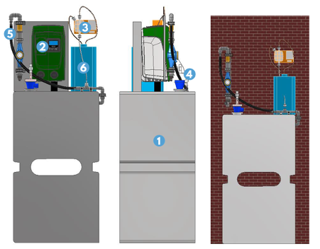
CASCADE AND POLISHER CONNECTION OVERVIEW
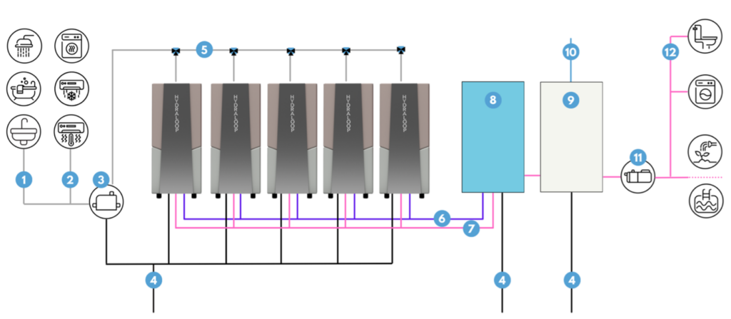
| 1 | Greywater supply from shower, bath and white hand basin |
| 2 | Condensation water supply from tumble dryer, air conditioning and heat pump |
| 3 | Lift pump optional, see Lift Pump Considerations |
| 4 | Sewer |
| 5 | Manifold |
| 6 | Cascade treated reusable water |
| 7 | Polisher post-treated reusable water |
| 8 | Polisher |
| 9 | Buffer tank |
| 10 | Backup water |
| 11 | Booster pump |
| 12 | Dedicated pipelines for reusable water output toilet flushing, washing machine, garden irrigation or swimming pool top-up (with auxiliary outlet) |
Recycle Ready Plumbing Diagram – Cascade and Polisher
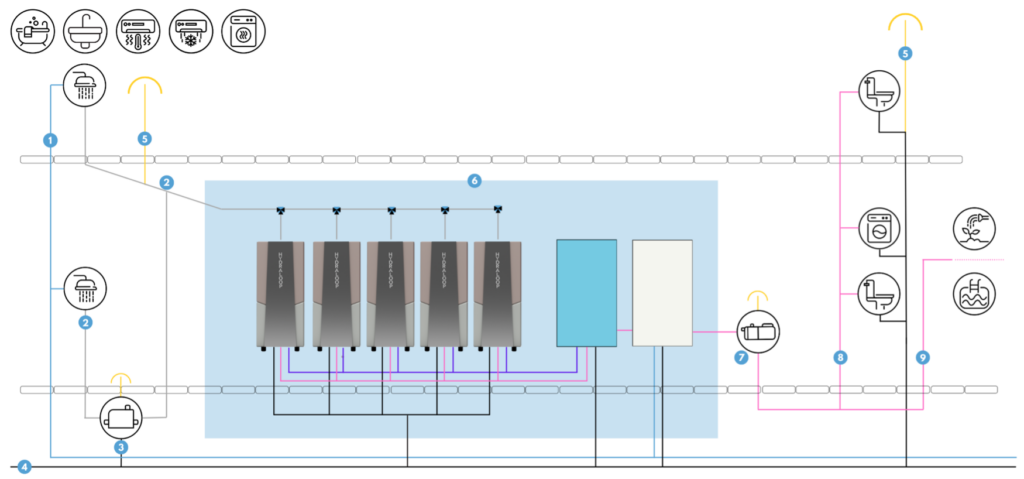
| 1 | Greywater supply from a higher floor shower, bath, hand basin, and/or condensation water supply from tumble dryer, air conditioning and heat pump. |
| 2 | Greywater supply from the same floor shower, bath, hand basin, and/or condensation water supply from tumble dryer, air conditioning and heat pump. |
| 3 | Lift pump (optional) |
| 4 | Sewer |
| 5 | Ventilation |
| 6 | Area and plumbing for Hydraloop Cascade and Polisher, managed by Hydraloop installer |
| 7 | Booster pump (optional) |
| 8 | Dedicated pipelines for reusable water output for toilet flushing and washing machine (pressurized). |
| 9 | Dedicated pipelines for reusable water output for topping up swimming pools and garden irrigation (non-pressurized). |
POLISHER CONNECTIONS
| Connection | Thread type | Diameter |
| Auxiliary outlet | 3/4” (male) | – |
| Standard output | 3/4” (male) | – |
| Backup water outlet | 3/4” (male) | – |
| Wastewater entrance | – | 32mm |
| Fresh water input (Buffer tank) | 3/4” (male) | – |
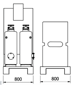
POLISHER DIMENSIONS AND WEIGHTS
| Hydraloop models | Height (mm) | Width (mm) | Length (mm) | Dry weight (kg) | Wet weight (kg) |
| Polisher | 1800 | 800 | 600 | 167 | 267 |
| Buffer tank | 1800 | 800 | 600 | 50 | 450 |
| Hydraloop models | Height (inches) | Width (inches) | Length (inches) | Dry weight (pounds) | Wet weight (pounds) |
| Polisher | 70.9 | 31.5 | 23.6 | 368 | 588 |
| Buffer tank | 70.9 | 31.5 | 23.6 | 110 | 992 |
POLISHER TECHNICAL SPECIFICATIONS
General Polisher Specifications
| Dimensions | Height: 1800 mm | 70.9” Width: 800 mm | 31.5” Length: 600 mm | 23.6” |
| Cleaning capacity | 1700–8500 liters | 225-2250 gallons per day, depending on Cascade setup (2–10 devices) |
| Voltage | 100 / 240V, 24V internal |
| Frequency | 50/60 Hz |
| Peak power consumption | 1200W |
| Normal state power consumption | 100W |
| Internet | WiFi or UTP |
| Input water source | Hydraloop AUX connection only |
| Input water temperature | 10–30 °C | 50–86 °F |
| Sound Level | ± 48 dB |
| Filtration technique | Sand/GAC* |
| Sand filter volume weight | 50 kg |
| GAC* filter volume weight | 20 kg |
| Sand mesh size | 0.4 – 0.8 mm |
| GAC* mesh size | 0.80 – 1.0 mm |
| Residual disinfection technique | Solenoid dosing pump (0.375 ml/pulse) |
| Disinfectant | Hypochlorite 12,5% |
| Dosing (programmable) | Standard 2ppm (= 0.2 mg/L) |
| Standard output pressure | 3 bar |
| Standard output flow | 60 L/min |
*Granulated Activated Carbon
Cascade and Polisher Water Quality
| Hydraloop Cascade Treated Reusable Water Quality | |
| CBOD5 | <10 ppm (mg/L) – AVG |
| TSS | <10 ppm (mg/L) -AVG |
| Turbidity | <5 NTU – AVG |
| E. coli | <14 MPN/100 mL |
| pH | 6-9 |
| Hydraloop Polisher Post-treated Reusable Water Quality | |
| CBOD5 | <10 ppm (mg/L) – AVG |
| TSS | <10 ppm (mg/L) -AVG |
| Turbidity | <2 NTU – AVG |
| E. coli | <1 MPN/100 mL |
| pH | 6-9 |
POLISHER COMPONENT OVERVIEW
Set-Up A – Residual Disinfection
| 1 | Buffer tank |
| 2 | Electrical cabinet |
| 3 | Water pump |
| 4 | Dosing pump |
| 5 | Back-up water supply |
| 6 | Circulation pump |
Set-Up B – Residual Disinfection And Sand Filter
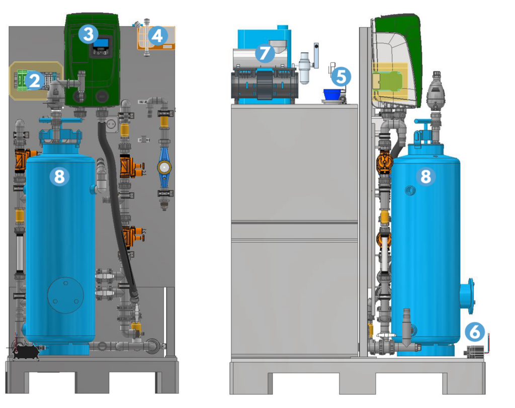
| 1 | Buffer tank |
| 2 | Electrical cabinet |
| 3 | Water pump |
| 4 | Dosing pump |
| 5 | Back-up water supply |
| 6 | Circulation pump |
| 7 | Compressor |
| 8 | Sand filter |
Set-Up C – Residual Disinfection, Sand Filter And Activated Carbon Filter
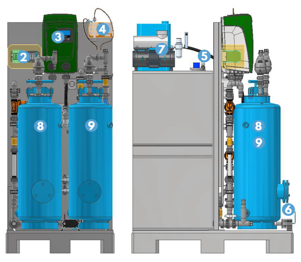
| 1 | Buffer tank |
| 2 | Electrical cabinet |
| 3 | Water pump |
| 4 | Dosing pump |
| 5 | Back-up water supply |
| 6 | Circulation pump |
| 7 | Compressor |
| 8 | Sand filter |
| 9 | Activated Carbon Filter |