INTRODUCTION #
Dear Hydraloop customer,
The Hydraloop Polisher is a water filtration unit for the post-treatment of reusable water coming out of a Hydraloop Cascade set-up. Treated water from the Hydraloop Cascade undergoes additional post-treatment by the Polisher, ensuring even lower turbidity levels and e-coli levels. The Polisher disinfects the reusable water to maintain the water quality from the distribution network to the end user.
The Hydraloop Polisher is directly connected to the Hydraloop Cascade setup, which can consist of up to 10 H600 devices. After post-treatment in the Polisher, the reusable water is stored in a buffer tank. From this buffer tank, the water can be distributed for non-potable usage such as toilet flushing, laundry, and garden irrigation. Depending on the building size, the buffer tank can also supply water to an external booster set-up. Additionally, the buffer tank functions as a contact tank for residual disinfection.
SAFETY #
General Safety Instructions #
WARNING
Before installing or operating any Hydraloop device, carefully review this manual.
The water produced by a Hydraloop device is non-potable. DO NOT use the output water for drinking purposes. Be aware that the backup water outlet and non-potable outlet are situated close by.
Only Hydraloop staff, certified Hydraloop partners, or authorized installers should open or service the device to minimize the risk of electric shock.
Follow the installation manual to ensure the safe and proper installation of the Hydraloop device.
WARNING
- If the power cable is damaged, it should be replaced by Hydraloop staff, a certified Hydraloop partner, or authorized installers.
- Before servicing or conducting maintenance, ensure the Hydraloop device is disconnected from the backup water supply.
ATTENTION
After commissioning or performing any work on the Hydraloop device, it is essential to inspect all water lines thoroughly for leaks and potential cross-connections.
Recommendations #
ATTENTION
- Install the Hydraloop device indoors, maintaining an ambient temperature range of 14-40°C | 57-104°F.
- Avoid exposing the Hydraloop device to direct sunlight.
- Do not connect reusable water to a bidet and/or a toilet hand-shower.
- Ensure the Hydraloop device is always easily accessible for service and maintenance.
ATTENTION
- The Hydraloop device must be moved or transported in an upright, vertical position.
- Be careful to avoid any damage to the exposed underside of the device.
Responsibility and Liability #
MANUFACTURER
Hydraloop ensures the proper functioning of the device in accordance with its general sales conditions. However, as the manufacturer, Hydraloop is not responsible in the following instances:
- Failure to follow instructions for Recycle Ready preparation, installation, maintenance, and/or operation of the device.
- Inadequate or insufficient maintenance of the device.
INSTALLER
The installer is responsible for the installation and activation of the Hydraloop device, ensuring compliance with local legislation, electrical, and plumbing codes. Key responsibilities include:
- Obtaining login details from the Hydraloop Sales Engineer.
- Conducting testing and activation through the HDM, along with performing all necessary checks.
- Maintaining a comprehensive commissioning report.
- Keeping a record of maintenance activities within their log.
- Providing a detailed explanation of the operation to the user/owner.
- Offering guidance on using the Hydraloop APP.
USER
For the best performance of the Hydraloop device, please follow these guidelines:
- Refer to the Owner Manual.
- Seek assistance from an approved, trained, and qualified installer for the Preparation, Installation, Testing, Verification, Activation, and regular maintenance of the device.
- Perform regular maintenance, with the interval determined by the quality of the input water.
Pipework Requirements #
The dimensions of Hydraloop devices, along with the distances and diameters of the connections, can be found in the ‘Recycle Ready Guide’ provided with the system. These dimensions have zero tolerances, as the components connected to the pipework are rigid. To ensure the correct configuration and dimensions for the connections, installers are given a frame to guide the construction or modification of the greywater collection and recycled water distribution networks.
A sign indicating the presence of a non-potable water system must be installed near the drinking water mains valve.
The distribution and collection pipework should be flushed and inspected for watertightness in accordance with EN 806-4, EN 12056-5, and EN 1610. After installation, the system will undergo a pressure test to check for cross connections.
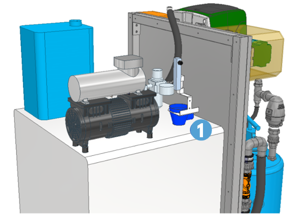
POLISHER COMPONENT OVERVIEW #
Set-Up A – Residual Disinfection #
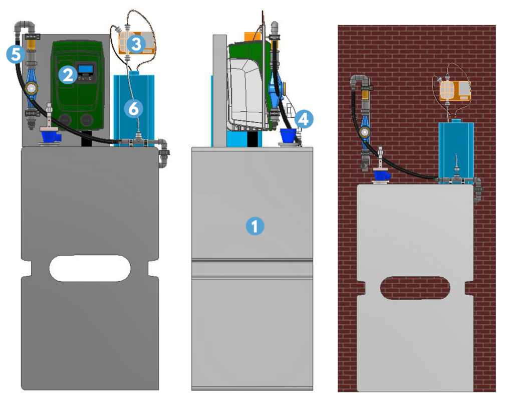
| 1 | Distribution tank |
| 2 | Electrical cabinet |
| 3 | Water pump |
| 4 | Dosing pump |
| 5 | Back-up water supply |
| 6 | Circulation pump |
Set-Up B – Residual Disinfection And Sand Filter #
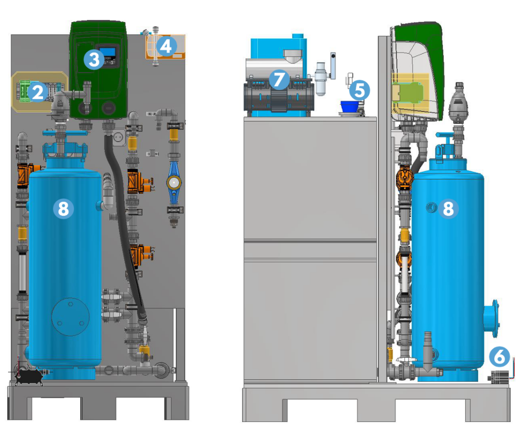
| 1 | Distribution tank |
| 2 | Electrical cabinet |
| 3 | Water pump |
| 4 | Dosing pump |
| 5 | Back-up water supply |
| 6 | Circulation pump |
| 7 | Compressor |
| 8 | Sand filter |
Set-Up C – Residual Disinfection, Sand Filter And Activated Carbon Filter #
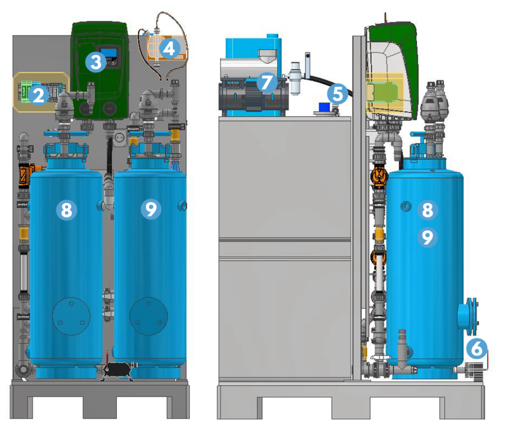
| 1 | Distribution tank |
| 2 | Electrical cabinet |
| 3 | Water pump |
| 4 | Dosing pump |
| 5 | Back-up water supply |
| 6 | Circulation pump |
| 7 | Compressor |
| 8 | Sand filter |
| 9 | Activated Carbon Filter |
POLISHER AND CASCADE CONNECTION OVERVIEW #
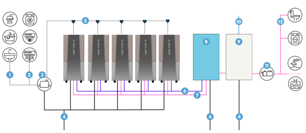
| 1 | Greywater supply for water from shower, bath and hand basin |
| 2 | Condensation water supply for water from tumble dryer, air conditioning and heat pump |
| 3 | Lift pump |
| 4 | Sewer |
| 5 | Manifold |
| 6 | Cascade treated reusable water from AUX output |
| 7 | Polisher post-treated reusable water as back-up water only applicable with set-up B and C |
| 8 | Polisher |
| 9 | Buffer tank |
| 10 | Backup water |
| 11 | Booster pump |
| 12 | Dedicated pipelines for reusable water output toilet flushing, washing machine, garden irrigation or swimming pool top-up (with auxiliary outlet) |
POLISHER CONNECTIONS #
| Connection | Thread type | Diameter |
| Auxiliary outlet | 3/4” (male) | – |
| Standard output | 3/4” (male) | – |
| Backup water outlet | 3/4” (male) | – |
| Wastewater entrance | – | 32 mm |
| Fresh water input (Buffer tank) | 1/2” (male) | – |
POLISHER DIMENSIONS AND WEIGHTS #
| Hydraloop models | Height (mm) | Width (mm) | Length (mm) | Dry weight (kg) | Wet weight (kg) |
| Polisher | 1800 | 800 | 600 | 167 | 267 |
| Buffer tank | 1800 | 800 | 600 | 50 | 450 |
| Hydraloop models | Height (inches) | Width (inches) | Length (inches) | Dry weight (pounds) | Wet weight (pounds) |
| Polisher | 70.9 | 31.5 | 23.6 | 368 | 588 |
| Buffer tank | 70.9 | 31.5 | 23.6 | 110 | 992 |
POLISHER TECHNICAL SPECIFICTIONS #
General Polisher Specifications #
| Dimensions | Height: 1800 mm | 70.9” Width: 800 mm | 31.5” Length: 600 mm | 23.6” |
| Cleaning capacity | 1700-8500 liters | 225-2250 gallons per day depending on Cascade size (2–10) |
| Voltage | 100 / 240V, 24V internal |
| Frequency | 50/60 Hz |
| Peak power consumption | 1200W |
| Normal state power consumption | 100W |
| Internet | WiFi or UTP |
| Input water source | Hydraloop AUX connection only |
| Input water temperature | 10–30 °C | 50–86 °F |
| Noise Level | ± 48 dB |
| Filtration technique | Sand/GAC* |
| Sand filter volume weight | 50 kg |
| GAC* filter volume weight | 20 kg |
| Sand mesh size | 0.4 – 0.8 mm |
| GAC* mesh size | 0.80 – 1.0 mm |
| Residual disinfection technique | Solenoid dosing pump (0.375 ml/pulse) |
| Disinfectant | Hypochlorite 12,5% |
| Dosing (programmable) | Standard 2ppm (= 0.2 mg/L) |
| Standard output pressure | 3 bar |
* Granulated Activated Carbon
Mechanical Specifications #
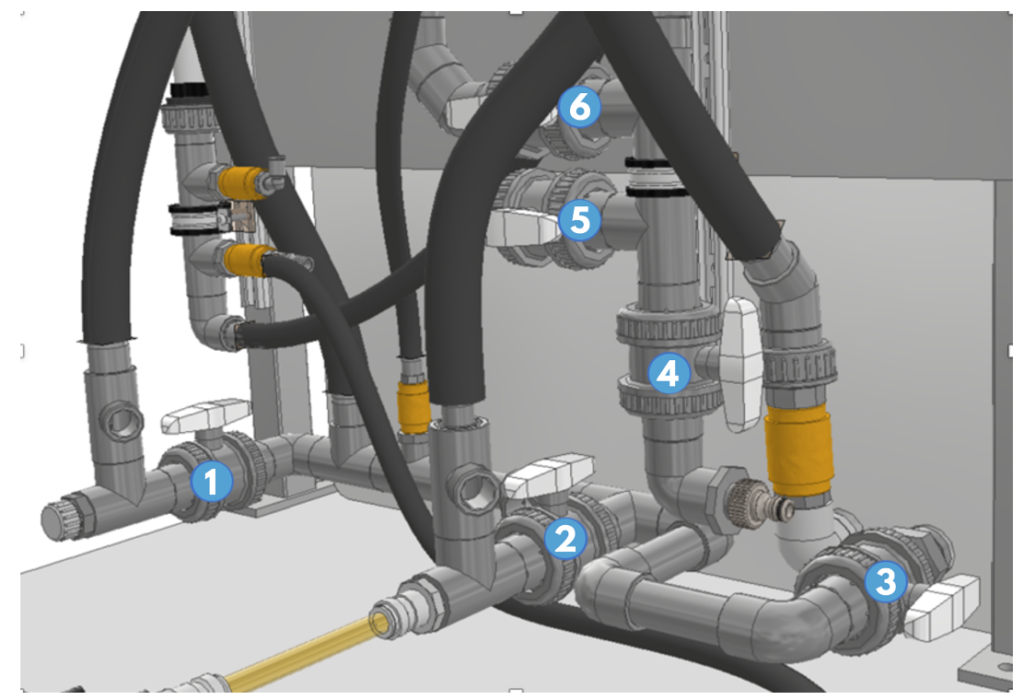
| 1 | Waste valve sand filter |
| 2 | Waste valve active carbon filter |
| 3 | Waste valve backwash tank |
| 4 | Cascade back-up valve (NO) |
| 5 | Auxiliary valve |
| 6 | Pump pressure valve |
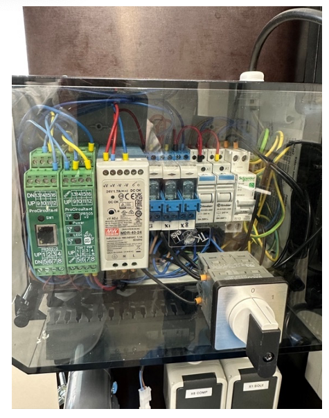
Electrical Specifications #
| Voltage | 240V, 24V internal |
| Peak power consumption | 1200W (1.2kw/h) |
| Normal power consumption | 100W (0.1kw/h) |
| Ampère | 5A |
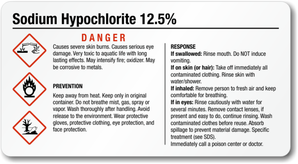
Chemical Specifications #
Hypochlorite 12.5%
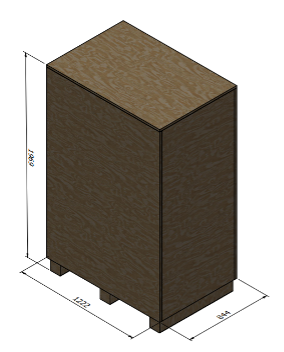
OFF-LOADING AND UNPACKING INSTRUCTIONS #
The Hydraloop Polisher will be delivered to its location on a half EURO pallet, enclosed in a protective wooden casing. To move the Polisher, a pallet truck or forklift is required for both transportation and relocation within the building. It’s important to note that the EURO pallet is integral to the Hydraloop Polisher structure and cannot be removed.
- When moving the Hydraloop Polisher, always ensure it is kept in an upright, vertical position. Placing it horizontally may cause damage to internal components and seals.
- Keep the wooden casing on the device until it reaches its final installation position. Only when it is near the final position should you remove the packaging and carefully lift the device from the plate.
STORAGE INSTRUCTIONS #
- For extended storage of the Polisher after usage, ensure that no liquid remains in the pipes, filters, and buffer tank.
- Clean the interior of the buffer tank and either replace or empty the filter tanks. Additionally, inspect and clean other parts for any issues.
- Store the Polisher indoors, maintaining humidity between 30% and 50%, and a temperature range of 10 – 25°C (50 – 77°F). Use the original packaging or casing.
- The Cascade setup is interconnected with the Polisher. If you need to store the Polisher separately, replace it with a buffer tank equipped with a distribution pump.
- If storing the entire Cascade and Polisher setup, please contact Hydraloop for assistance.
INSTALLATION CONSIDERATIONS #
Required Equipment #
For the installation of the Hydraloop Polisher, you will need at minimum a water pump wrench, a flat head screwdriver, and a socket wrench set.
Basic Installation Steps #
- Prior to installation, ensure that you are following applicable plumbing and electrical guidelines in your city or state/province and that your plumbing configuration is protected against backflow and cross connection, maintaining the safety of the public water supply.
- Position the Hydraloop Polisher and the buffer tank in its planned location.
- Connect the Polisher wastewater outlet to the sewer.
- Connect the incoming Cascade treated water to the Polisher inlet.
- Connect the backup water supply and open.
- Plug the power cord into wall socket.
- Connect the Polisher to the local online network via a WiFi- or Ethernet connection.
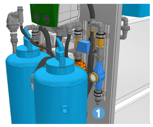
INSTALLATION INSTRUCTIONS #
Connect Flexible Hoses: Input from AUX Collection Cascade setup is located under the Polisher’s water meter.
Connect Backup Water: Connect the Backup Water from Cascade to Polisher using 32 mm pond hose.
Drain Polisher: Use a 32 mm pond hose for draining the Polisher.
Connect Back-up Water Supply to Buffer Tank: Fixed piping is required for this connection.
Connect Wall Socket: The connection is in the electrical cabinet.
Online connection #
WiFi Connection
- Switch on the Polisher. Once powered on, it will automatically create a Wi-Fi network (e.g., 00:AB:00:AB:11).
- On your smartphone, tablet, or computer, select this network and use the password ‘Hydral00p’.
- Verify the connection by checking if your device is connected to the selected network.
- Open an internet browser and type ‘192.168.4.1’ in the search bar. A page will open; choose the local network you want the Polisher to connect to, enter the password, and press ‘submit’.
- The Polisher is now connected to the local network.
NOTE
Ensure the correct entry of spaces, commas, and uppercase letters.
Ethernet Connection
If a WiFi-connection is not available, please use a LAN connection to connect the Polisher to the local network. The Ethernet connection is located in the electrical cabinet.
MAINTENANCE #
WARNING
Only Hydraloop staff, certified Hydraloop partners, or authorized installers are allowed to open or service the Hydraloop Polisher.
Required Equipment #

For all Hydraloop Polisher related service and maintenance activities, you will need to wear gloves, safety glasses, protective clothing, and a mask.
Maintenance Period 0.5 years (6 Months) – Polisher Setup C #
1. Activated carbon filter replacement
- Empty the activated carbon filter.
- Clean the inside of the filter with a water vacuum cleaner and a cloth.
- Fill the filter with activated carbon media. For the correct filter substance, see Section 6.1, General Polisher Specifications.
- After the filter has been re-filled, it must be flushed. Open the carbon filter waste valve by hand. Connect the back-up water and flush the system.
WARNING
Do not use more than 3 to 4 bar for flushing.
NOTE
The sand filter functions as a filtration that also provides protection for the activated carbon filter.
2. Chlorine Maintenance
- Check the chlorine maintenance schedule in the HDM.
- Depending on water consumption and treatment, replace the chlorine (12.5%). Please contact a Hydraloop Sales Engineer via email support@hydraloop.com.
WARNING
Adjusting the dosage independently is strictly prohibited and must always be coordinated with Hydraloop.
Maintenance Periode 5 Years – Polisher Setup B and C #
Sand filter replacement
- Empty the sand media from the filter housing.
- Clean the inside of the filter with a water vacuum cleaner and a cloth.
- Fill the filter with sand media.
- For the correct media, please refer to Section 6.1, General Polisher Specifications and contact a Hydraloop Sales Engineer via email support@hydraloop.com.
WARNING
Do not use more than 3 to 4 bar for flushing.
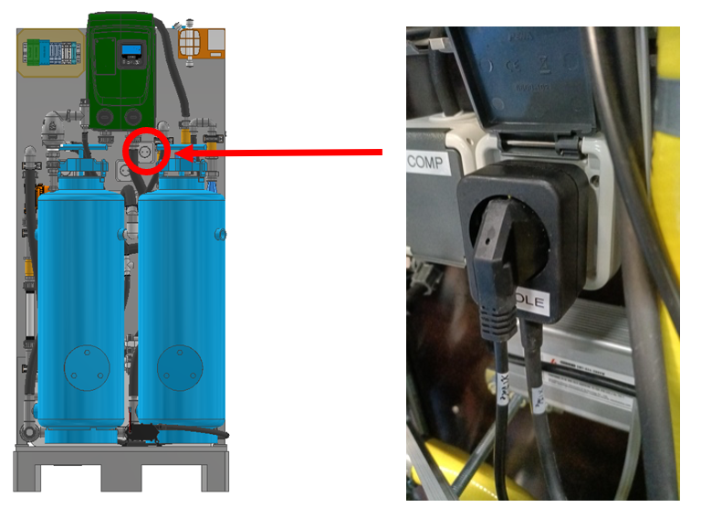
POLISHER FUNCTIONS #
Bypass Mode
In case of a Polisher malfunction, it is still possible to distribute water to toilets, laundry, garden or pool. Set to Bypass Mode, the Polisher distributes only backup water until the malfunction is resolved.
- Unplug the power plug from the Polisher, see figure 9 and 10.
- Plug the Polisher power plug in a powered wall socket next to the Polisher.
Once the issue is solved and the Bypass Mode is no longer required, unplug the power plug from the powered wall socket and replace it into the Polisher to return to normal operation.
Back-wash
This function reverses the current through the sand filter, directing the largest contaminants to the drain for removal.
HDM
The HDM provides user statistics and allows authorized personnel to perform maintenance on the Polisher.
BMS – Building Manager System Feature
Once connected to the local network, the Polisher can be monitored through the Building Manager System.
DEVICE MALFUNCTION AND REPAIR #
If the Polisher appears to be malfunctioning, please activate the ‘Bypass mode’ (See Section 12, Polisher Functions) and reach out to a Hydraloop Sales Engineer by emailing support@hydraloop.com.
Potential malfunctions of the Polisher are:
No water pressure
Activate the Bypass Mode, see Section 12. Unplug the backup water valve and connect it to a wall socket. The buffer tank will fill until the float switches, allowing the Polisher to distribute water. For further assistance, please contact a Hydraloop Sales Engineer via email at support@hydraloop.com.
Smelly water
Foul-smelling reusable water may have one of three possible causes:
- Clogged filters. Check the filters for clogs and review the last service date. For service terms and maintenance protocols, see Section 13.
- Pump problems. If the main pump or circulation pump is defective, please reach out to a Hydraloop Sales Engineer via email at support@hydraloop.com.
- Chlorine. Ensure that the chlorine dosage is appropriately set. There may be a malfunction in the chlorine pump. For assistance, contact a Hydraloop Sales Engineer via email at support@hydraloop.com.
WARNING
Adjusting the chlorine dosage independently is strictly prohibited and must always be coordinated with Hydraloop.
DECOMMISSIONING #
When removing the Polisher from service, ensure that no liquid remains in the pipes, filters, and buffer tank. Clean the interior of the buffer tank and either replace or empty the filter media tanks. If necessary, clean other components and inspect for any issues.
For details on proper storage procedures, see Section 9, Storage Instructions.
As the Cascade setup is linked to the Polisher, replace the Polisher with a buffer tank equipped with a distribution pump.
For assistance with storing the entire Cascade and Polisher setup, please contact Hydraloop by emailing support@hydraloop.com.
DISMANTLING AND DISPOSAL #
If the Polisher is disassembled or discarded for storage or demolition, kindly get in touch with a Hydraloop Sales Engineer via email at support@hydraloop.com.
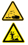
ENVIRONMENT #
The Polisher uses Chloride (12.5%). Handle this product with care and read the safety instructions on the packaging before use. The chloride dosage is correctly adjusted during installation.
WARNING
Adjusting the chlorine dosage independently is strictly prohibited and must always be coordinated with Hydraloop.
WARRANTY #
For detailed information on the warranty coverage, please review your warranty certificate. It is essential to ensure that all your personal information is accurately entered into your Hydraloop APP.
Under this Factory Warranty (“Warranty”), Hydraloop guarantees to the original purchaser of the Hydraloop device (referred to as the “Product”) as outlined in Part 1 of the Warranty Policy under “Customer,” that the Product will be free from material Defects for a period of two (2) years from the date of the original purchase invoice from Hydraloop or one of its authorized Partners, unless local jurisdiction mandates a longer term. In these warranty terms, a “Defect” refers to a manufacturing or design flaw that significantly affects the Product’s use, solely attributable to Hydraloop, and not detectable at the time of Product delivery.
To assist Hydraloop device owners in entering their information, contact details, and physical address into the warranty section on the Hydraloop APP, the Hydraloop installer will provide support.
AVERAGE REUSABLE WATER QUALITY #
| Hydraloop Cascade Treated Reusable Water Quality | |
| CBOD5 | <10 ppm (mg/L) – AVG |
| TSS | <10 ppm (mg/L) -AVG |
| Turbidity | <5 NTU – AVG |
| E. coli | <14 MPN/100 mL |
| pH | 6-9 |
| Hydraloop Polisher Post-treated Reusable Water Quality | |
| CBOD5 | <10 ppm (mg/L) – AVG |
| TSS | <10 ppm (mg/L) -AVG |
| Turbidity | <2 NTU – AVG |
| E. coli | <1 MPN/100 mL |
| pH | 6-9 |
GLOSSARY OF TERMS #
Auxiliary Outlet– This valve allows for the distribution of reusable water to be used for the garden, irrigation, or pool top-up (depending on your region). This outlet is non-pressurized.
Backup water– Water that is used as a main source of water in the building. This could be tap water, municipal water, well water, rain water etc. Another term for backup water is ‘mains water’.
Blackwater – Contaminated wastewater containing pathogens from human waste and other organic materials. This waste stream can come from toilets, bidets, hand showers, floor drains, dishwashers, and kitchen sinks.
Booster pump – A booster pump increases the water pressure in a plumbing system. It boosts the flow of water, ensuring adequate pressure for various applications such as toilets, faucets, and irrigation systems.
Buffer tank – A storage container used in plumbing and HVAC systems to store excess water. It helps regulate pressure fluctuations, smooth out flow variations, and maintain system stability by providing a reserve of water to compensate for sudden demand changes.
Cascade treated reusable water – Cascade treated reusable water refers to greywater that has been processed through a Hydraloop Cascade system.
Greywater – Lightly contaminated domestic water coming from the drains of baths, showers and washing machines.
Hydraloop Device Manager (HDM) – Online monitoring system for the Hydraloop device. During installation, this platform is used for testing, verification, and activation of the Hydraloop device. After installation, the HDM is used for monitoring, maintenance, troubleshooting and ticket generation. Before installation of a Hydraloop device, the HDM requires login credentials, provided by Hydraloop. Please ask your Hydraloop installer if your device has a viable login-code before installation.
Inlet diverter – This optional valve allows for the intake of greywater from sources other than the shower/bath i.e. the washing machine. By adding this valve to the inlet of the Hydraloop device, greywater from the washing machine can be treated for reuse.
Polisher – The Polisher is a water filtration unit for the post-treatment of reusable water coming out of a Hydraloop Cascade set-up. Treated water from the Hydraloop Cascade undergoes additional post-treatment by the Polisher, ensuring even higher water quality.
Polisher post-treated reusable water – Water post-treated by a Polisher refers to Cascade treated water that has been processed by the Hydraloop Polisher.
Recycle Ready Guide – A guide provided by Hydraloop, aimed at device owners, plumbers, and contractors. The Recycle Ready Guide explains how to prepare and configure the plumbing network in a building, so it is ready to receive and recycle greywater.
Recycle Ready Checklist – Once preparations are complete, the Hydraloop owner and construction professional verify and co-sign the ‘Recycle Ready Checklist’. Then, the Hydraloop owner sends the co-signed Checklist to their Hydraloop Partner. Without a signed and verified Recycle Ready Checklist, an installation date cannot be planned.
Reusable water – Greywater that has undergone various steps of treatment to be reused for non-potable uses like toilet flushing, laundry and/or outdoor uses (garden irrigation, pool top-up).
Start-up Time – The Hydraloop device requires a minimum of 21 days (3 weeks) or 20 showers to develop the biological treatment process in the T2 tanks and become fully operational. If the device has not sensed 20 showers by 21 days of operation, the start-up time will last longer.
Ventilation – This is placed along the greywater line to prevent anti-siphoning of water out of airlock. Ensure that the greywater input and sewage output both have proper two-way ventilation. Ventilation for greywater input should be above all greywater lines and end outside the building.
This document and its contents exclusively belong to Hydraloop Systems B.V. and must not be reproduced, whether in part or in whole, without the prior written consent of Hydraloop Systems B.V. Hydraloop retains the right to modify the specifications provided in this document.
Hydraloop products are safeguarded by existing patents and patents pending. The Hydraloop brand name is a registered trademark.
Hydraloop Systems B.V.
Wetsus Building,
Water Campus
Oostergoweg 9
8911 MA Leeuwarden
The Netherlands
+31 88 100 3500
Hydraloop Inc.
228 E. 45th Street,
Suite 9E New York,
NY 10017,
United States of America
+1 414 89 500 21
Hydraloop MENA LLC
Business Centre 1
M Floor, The Meydan Hotel
Nad Al Sheba, Dubai
U.A.E.
+971 5 228 457 00
E-Mail: support@hydraloop.com
Website: www.hydraloop.com