Hydraloop H300 holds NSF/ANSI 350 Class R and is third party validated.
Safety #
General Safety Instructions #
– WARNING –
- Before installing or operating any Hydraloop device, carefully review this manual.
- The water produced by a Hydraloop device is non-potable. DO NOT use the output water for drinking of preparing food. Be aware that the backup water inlet and non-potable outlets are situated closely together.
- Only Hydraloop staff, certified Hydraloop partners, or authorized installers should open or service the device to minimize the risk of electric shock.
- Follow the installation manual to ensure safe and proper installation of the Hydraloop device.
– WARNING –
- If the power cable is damaged, it should be replaced by Hydraloop staff, a certified Hydraloop partner, or authorized installers.
– ATTENTION –
During commissioning and performing any work on the Hydraloop device, it is essential to inspect all water lines for leaks and potential cross-connections.
Recommendations #
– ATTENTION –
- Install the Hydraloop device indoors, maintaining an ambient temperature range of 14-35 °C | 57-95 °F.
- The Hydraloop device is not UV or IP-rated. Avoid exposure to direct sunlight and water ingress.
- Ensure the relative humidity in the room is below 70% to prevent corrosion on the electrical components.
- Do not connect reusable water to a bidet and/or a toilet hand-shower.
- Ensure the Hydraloop device is always easily accessible for service and maintenance. This means at least 80 cm in front of device.
- The Recycle Ready Pre-Checklist and Confirmation Checklist must be filled in and submitted. Failure to do so may result in voiding warranty.
– ATTENTION –
- The Hydraloop device must be moved or transported in an upright, vertical position.
- Be careful to avoid any damage to the exposed underside of the device.
Responsibility and liability #
Manufacturer #
Hydraloop guarantees the proper working of the device according to its general sales conditions.
As a manufacturer, Hydraloop is not liable in the following cases:
- Failure to follow instructions for Recycle Ready preparation, installation, maintenance, and/or operation of the device
- Inadequate or insufficient maintenance of the device
- Failure to submit a signed copy of the Recycle Ready Pre-Checklist and Recycle Ready Confirmation Checklist.
- The front base plate is a galvanized steel plate. Some superficial scratches may be present from the manufacturing process. This is unavoidable and part of the natural look. Alternatively a magnetic design cover can be ordered.
Installer #
The following items is the installer’s responsibility:
- Installation shall be according to local legislation, electrical and plumbing codes
- Installer must have obtained login details from a Hydraloop Sales Engineer
- Testing and verification via the HDM with all necessary checks
- Maintain commissioning report and record of maintenance within their log
- Explanation of operation as well as the Hydraloop APP to the user/owner
User #
To ensure optimal functioning of the Hydraloop device, please observe the following:
- The Owner Manual
- The Hydraloop Care Guide
- The assistance of a qualified installer for preparation, installation, testing, verification, activation, and regularly scheduled maintenance of the device
- Regular maintenance is required in accordance with our maintenance guide
- The operation of the Hydraloop APP
– WARNING –
Hydraloop device is designed for ‘normal usage’ and is not designed to receive solid materials like stones, chemicals, paint residues, hair dye, bleach, disinfectants, or any other matter that is unusual for shower/bath and washing machine greywater. In the event these substances enter the H300, it can be damaged, and the water treatment can be affected. There is a function in the APP where the greywater from the T1 tank can be wasted to the sewer if you suspect foreign matter has entered the Hydraloop device (i.e., hair dye or bleach).
Note: Hydraloop Systems BV is not liable for any damage if the above or any other abnormal substances enter the H300.
Pipework requirements #
The greywater collection pipework must be:
- Dedicated to greywater (no kitchen, dishwasher, floor drains, human waste, etc.)
- Gravity drained (not pressurized) and fully vented greywater drain
- Installed with an overhead bypass. Not restricting greywater drainage flow
The greywater collection pipework shall prevent water from other sources entering the greywater system (see recycle ready guide).
All non-potable tap points shall be identified as such. 3 stickers with non-potable water markings according to EN 16941-2 are included with every Hydraloop.
The distribution and collection pipework shall be flushed and inspected for watertightness according to EN 806-4 and EN 12056-5 and EN 16941-2. After installation the system should be tested for cross connections. A testing procedure can be found further in this installation manual.
Requirements #
Below are the system requirements. More information can be found in our FAQ:
| Location/placement: | Inside the building thermal envelope. Hydraloop is not IP rated or UV resistant. Avoid direct sunlight and rain. Maximum RH-value: 70% Recommended positions are: mechanical or technical room, garage, laundry and garage. Due to possible 24-hour sound production, it is not recommended in or adjacent to living space or quiet rooms. For systems sounds, see Specifications. |
| Temperature | Average operational ambient temperature 14-35 °C. |
| Service space: | 80 cm in front of Hydraloop. |
| Greywater inlet: | 40 mm O.D. PVC. height min. 2200 mm CL. Only shower/bath water, washing machine (max. 1, with inlet diverter). No kitchen sinks, dishwashers, floor drains or human waste. Do not sit/stand on the Hydraloop. Do not use it for storage, leave top free for access. |
| Drainage connection: | 110 mm. Hydraloop has 40 mm I.D. union clamp connection. Max. discharge volume is 2 l/s at cleaning cycle |
| Electrical power: | 230 V, 50 Hz, 15-16 Amp (120 V, 60 Hz, 15-16 Amp US/CAN) earthed wall outlet within 1.2 m from top center of Hydraloop |
| Internet connection: | Ethernet cable or; 2.4 GHz Wi-Fi with WPA or WPA2, no captive portal. If internet access is restricted by a firewall, ensure TCP post 443 is open. Distance Wi-Fi router to Hydraloop > 1 m. |
| Water hardness: | max. 7° dH / 7 GPG / 120-180 ppm |
| Req. ceiling height: | 2400 mm |
Hydraloop H300 specifications #
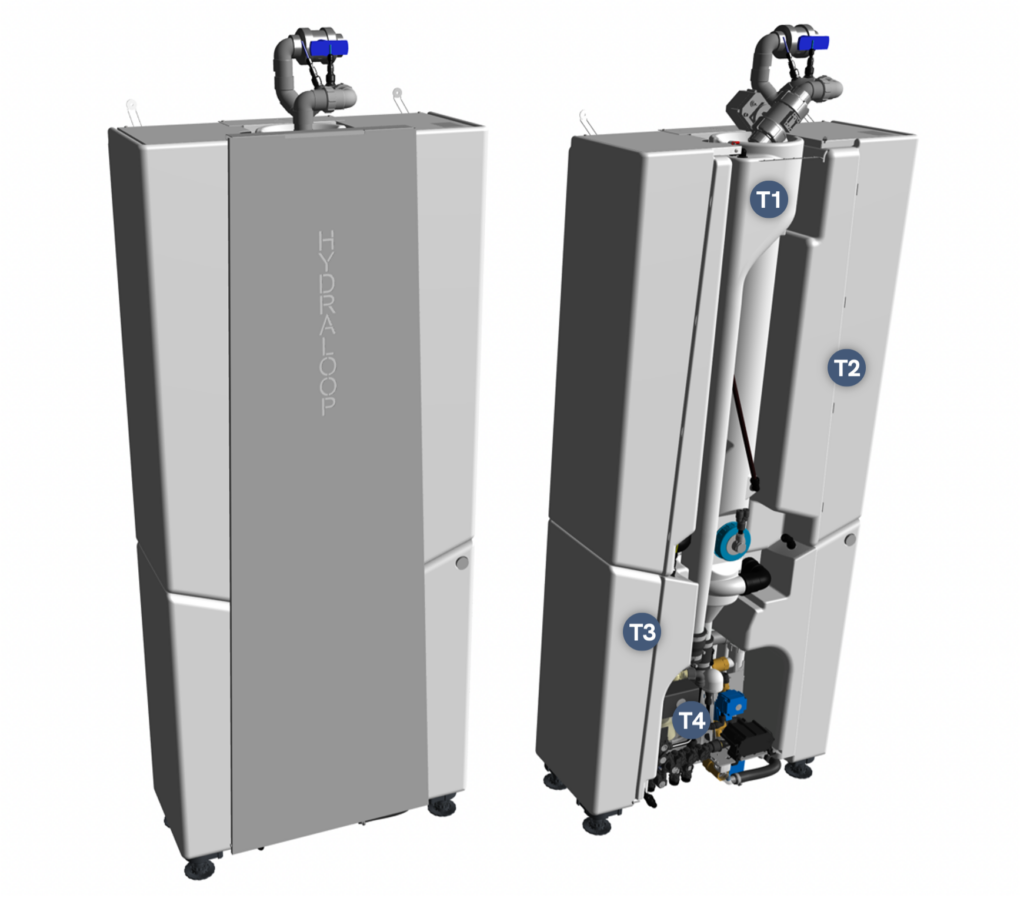
Image: Hydraloop H300. Left; with front plate, standard inlet. Right; without front plate and optional inlet diverter.
The image above also indicates the 4 tanks of which the Hydraloop consists of:
- T1; Greywater inlet tank
- T2; Bioreactor tank with moving bed bioreactor (MBBR)
- T3; Storage tank which holds recycled water
- T4; Tank for backup water connection, complete with safe air gap
Output specifications #
The recycled water from Hydraloop is suitable for toilet flushing, washing machine, garden irrigation, topping up swimming pool and cleaning purposes.
| Output Outlet | Water Delivery | Pipe size |
| Toilet | permanently pressurized | 1/2″ BSP |
| Washing machine | permanently pressurized | 1/2″ BSP |
| Auxiliary * | only pressurized before transfer to T3 when T3 is full | 1/2″ BSP |
*Auxiliary outlet will be activated after order as add-on.
All tap points that receive recycled water from the Hydraloop must be identified with a non-potable water sign (3 stickers come with device).
Distribution pump performance: #
- Nominal pump pressure: 2.1 bar / 210 kPa
- Nominal flow: 12 l/min
Input specifications #
Hydraloop requires a backup water connection. The backup water connection is in the distribution unit. Backup water can be mains (tap) water, treated rainwater or treated well water.
| Input Outlet | Water Delivery | Pipe size |
| Backup water | permanently pressurized min. 12 l/min required | 1/2″ BSP |
The backup water enters the Hydraloop via a safe air gap (T4), ensuring no possible connection between (recycled) grey water and backup water.
Specifications #
| Hydraloop H300 | |
| Volume | 300 liters |
| Nominal cleaning capacity | 360 liters (depending on user behavior) |
| Voltage | 120 / 240V, 24V internal |
| Average power consumption | 220 kWh/year, 25W during treatment |
| Internet | The Hydraloop device needs to be connected with internet through an ethernet cable or an internal Wi-Fi-network. Note: Wi-Fi router must be > 1m from Hydraloop |
| Greywater input sources (possible) | Shower, Bath and Washing machine (with inlet diverter) |
| Sound Pressure (Lpa) level at various treatment stages | Interval / duration | |
| Airpump | 29 dB(A) | Daily / long |
| Distribution pump | 29 dB(A) | Daily / with use |
| Greywater flow into Hydraloop | 49 dB(A) | Daily / with use |
| Backup water filling | 48 dB(A) | Weekly / depending on user behavior |
| Inlet diverter open/close | 50 dB(A) | Depending on user behavior / when recycling greywater from washing machine |
| Self-cleaning cycle | 50 dB(A) | Weekly / short |
Dimensions and weights #
| HYDRALOOP MODEL | WIDTH (MM) | DEPTH (MM) | HEIGHT (MM) | DRY WEIGHT (KG) | WET WEIGHT (KG) |
| H300 (Inlet standard) | 800 | 360 | 1985 | 82,5 | 383 |
| H300 (Inlet Diverter) | 800 | 360 | 1990 | 83,5 | 384 |
| H300 PACKAGED | 815 | 800 | 2050 | 90,5 – 92 | – |
For technical detailed drawings, see the following pages.
What’s in the box? #
The Hydraloop comes with the following items:
| Hydraloop H300 | 230V | ||
|---|---|---|
| Quantity | Part number | Description |
| 1 | HYD0089 | PVC Hand Ball Valve Ø40mm I.D. |
| 1 | HYD0416 | Elbow PVC 90° – Ø40 MF |
| 2 | HYD0401-1 | Tube PVC Ø40×3 – L70mm |
| 2 | HYD0408 | Flexible converter Ø50xØ40 |
| 1 | HYD0577 | Power Plug TYPE G |
| 1 | HYD0579 | Power Plug TYPE F |
| 1 | HYD0501 | Quick Reference Guide H300 |
| 4 | HYD0233 | Flexible water hose DN8 FM1-2 – FM1-2 – L500 |
| 1 | HYD0524 | Coarse water filter set |
Installation steps #
– Important –
Ensure that you are following the plumbing and electrical regulations for your region and that your plumbing configuration is protected against backflow and cross connection to maintain the safety of the public water supply.
– Important –
The greywater inlet should be connected using the manual shut-off valve to be able to isolate the Hydraloop device.
Installation steps (more in-depth information below):
- Position the Hydraloop device in its planned location
- Secure the Hydraloop from falling using the anti-fall straps
- Remove the front plate
- Connect the H300 wastewater outlet to sewer
- Connect the incoming greywater to the inlet at the top of T1, via the inlet manifold
- Connect the overhead bypass to sewer
- Connect light and dark blue pressure tubes to inlet manifold. In downstream flow direction:
- Dark Blue
- Light Blue
Resulting in the light blue pressure tube inserted closest to the Hydraloop inlet.
- Connect the backup water supply using the provided hose, installing an isolation valve
- Open the valve
- Connect the recycled water outlets “WC”, “WM” and/or “AUX” to the dedicated recycled water lines using the flexible hoses provided
- Plug the power cord into the wall socket and turn the power switch ON
- Verification and Activation using the HDM (optional: with Hydraloop Sales Engineer)
- Perform a cross-connection test protocol to ensure no cross-connections are present
Offloading and unpacking #
For stability, the Hydraloop device will be transported using a large footprint wooden pallet. The Hydraloop is wrapped in protective packaging. The Hydraloop is strapped to a small footprint pallet, which can be detached for easy internal transportation. Please take the following precautions:
– WARNING –
When moving the Hydraloop device, it is important to always keep it in an upright, vertical position. A horizontal position may cause damage to the devices’ internal components and seals.
– Important –
Leave the protective packaging on the device until it’s placed at its final installation position.
- When it is near its final position, remove the packaging and carefully place the device.
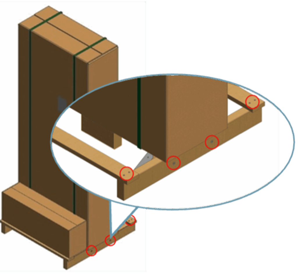
Large footprint to small footprint pallet:
To reduce the footprint of the pallet, take the following steps:
- Unscrew all screws on both sides as indicated in image below, to remove the bottom beams from the main wooden plate.
- Once the large footprint pallet is dismantled, leave the Hydraloop device strapped to the small footprint, transportation plate. It can then be easily moved with a 2-wheel trolley/dolly.
– WARNING –
Please do not remove the Hydraloop device from transportation plate until it has reached its final location. Do not use any apparatus underneath the device to move it as this will cause damage to the exposed distribution unit at the underside.
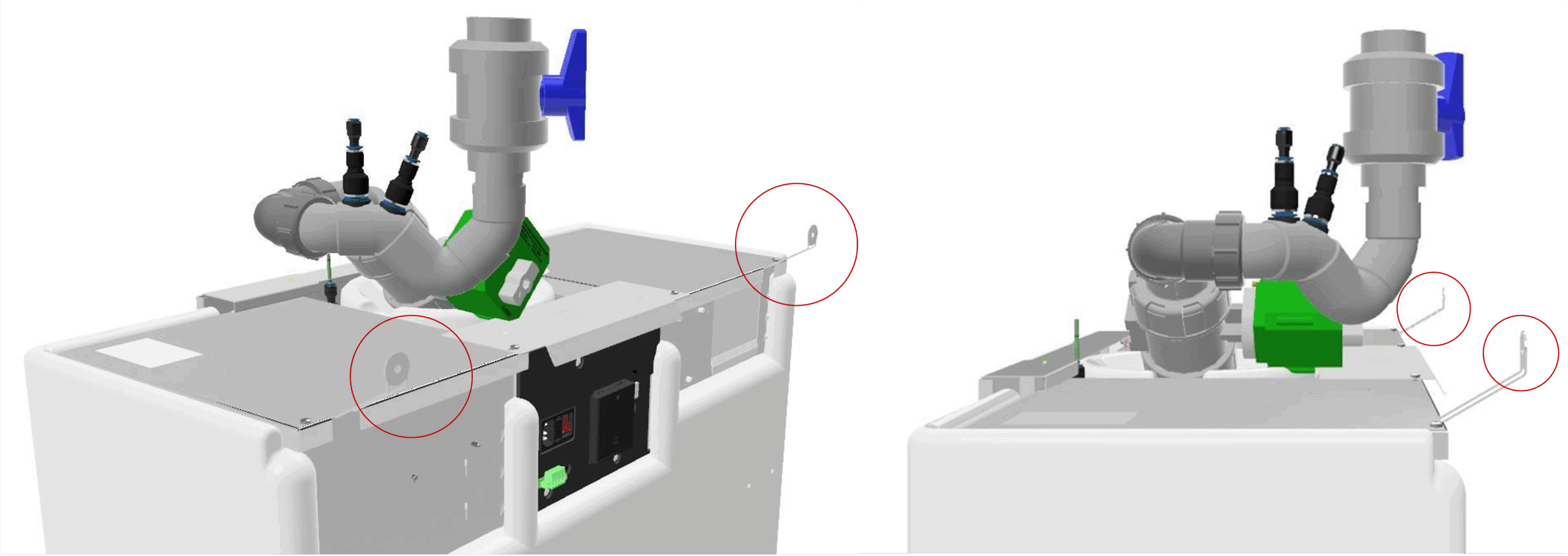
Safety strap #
The H300 should be installed against a wall, leaving room for the electrical connection. The device should be secured to the wall to prevent it from falling over. The Hydraloop has two adjustable anti-fall straps. Adjust the bend plates according to its desired position. Then affix bend plates to the wall.
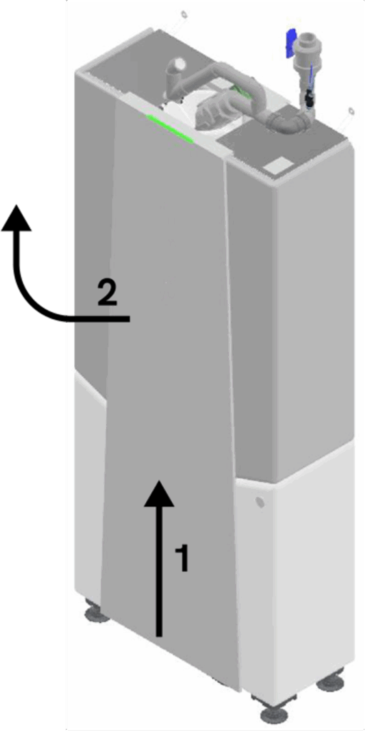
Front plate removal #
To remove the front plate, place a lever on the bottom of the front plate to carefully lift the plate upwards. The plate is being held in its position due to its shape. Once it moves upwards it will be free to remove forward. Disconnect the LED light connection from the front plate and put the plate aside.
| 1 | Carefully wedge a wooden (i.e. broomstick) or plastic tool between the bottom of the front plate and the floor and move the front plate upwards. |
| 2 | Remove the front plate off the device. Disconnect the earth wire and LED light connection from the top of the front plate. – Important – Note: place the front plate in such a way that it cannot fall and be damaged. |
Wastewater outlet installation #
The 40 mm | 1 1/2″ wastewater connection at the bottom of the Hydraloop needs to be connected to the sewer through the floor (Image XX (Option 1) or backwards into the wall (Image XX (Option 2).
We recommend a 110 mm drainage connection to connect into. During the weekly cleaning cycle of the Hydraloop T1 and T2 are being flushed at a volume of approx. 45 l/min. for the duration of approx. 1 – 2 minutes.
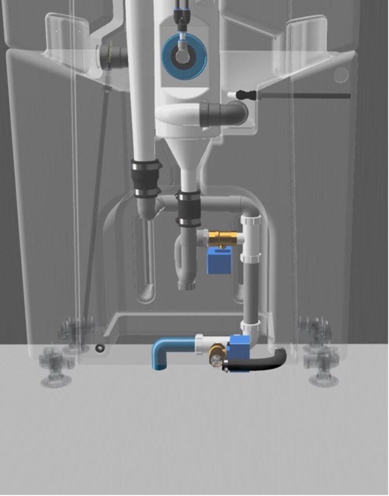
Image XX: Option 1: H300 drain to sewer connection through the floor.
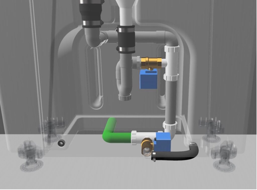
Image XX: Option 2: H300 drain to sewer connection through the wall.
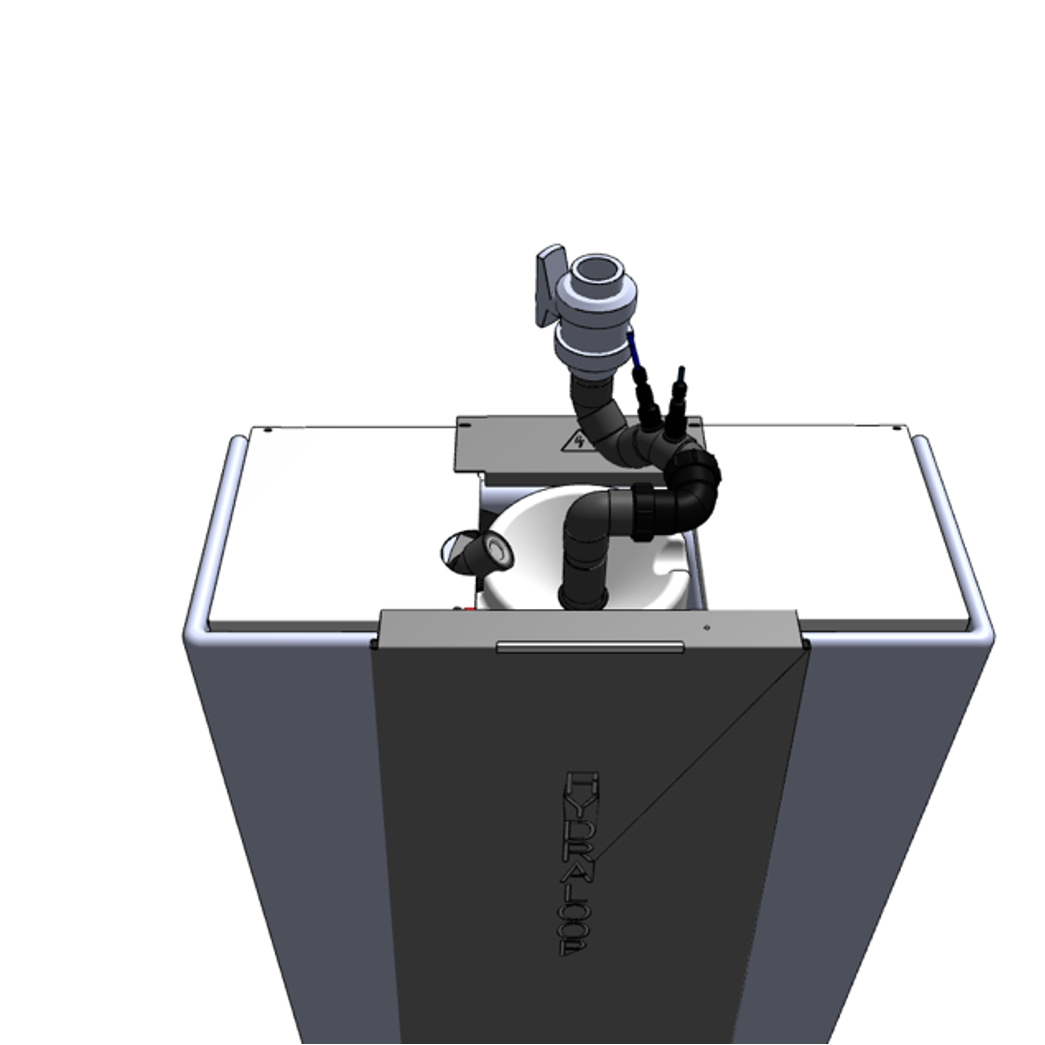
Inlet manifold assembly #
The inlet manifold come partly assembled. For the final assembly follow the steps written next to the image.
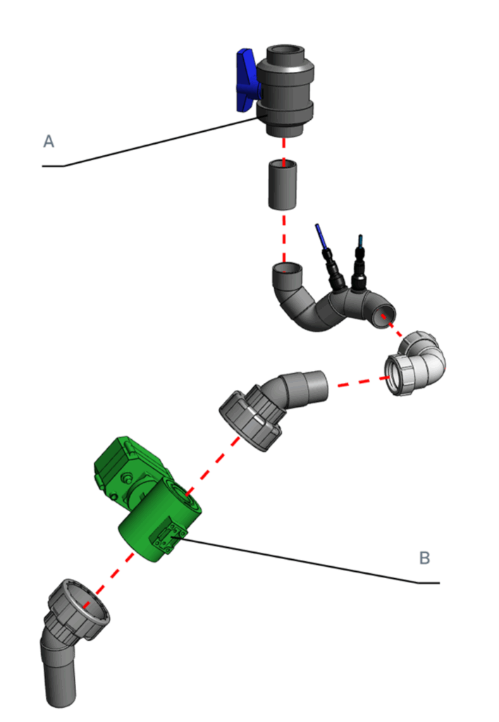
The manual isolation valve should always be installed. The valve (A) can be placed horizontal or vertical, depending on the orientation of the incoming greywater drain. For horizontal orientation use the PVC bend provided.
When the inlet diverter option is supplied, tighten the threaded union couplings (B) onto the motor valve.
Inlet manifold connection: 2 versions #
Standard inlet manifold #
Follow the steps below for the proper installation of the inlet manifold.
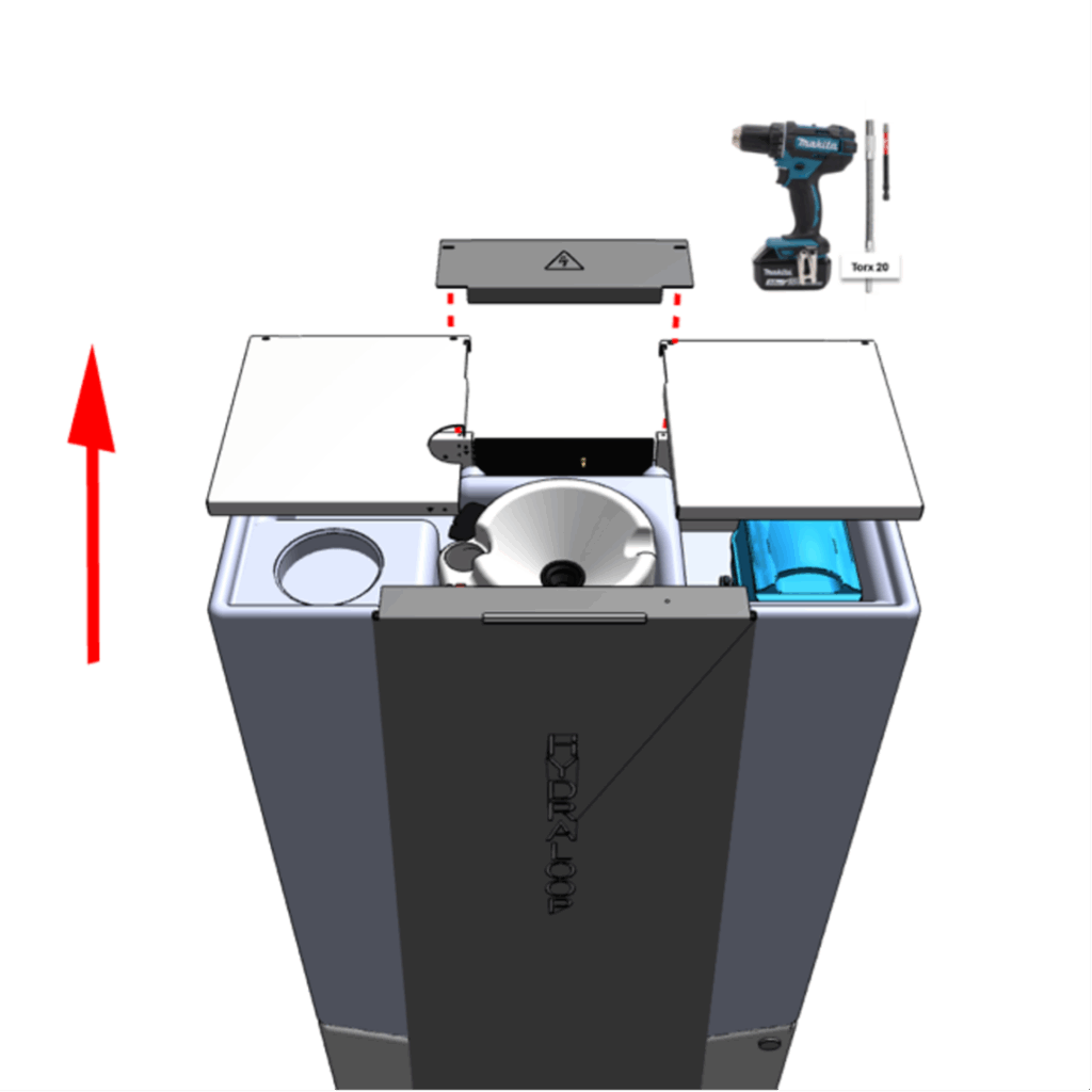
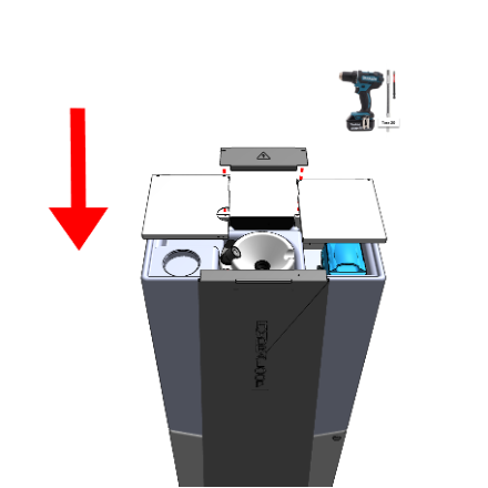
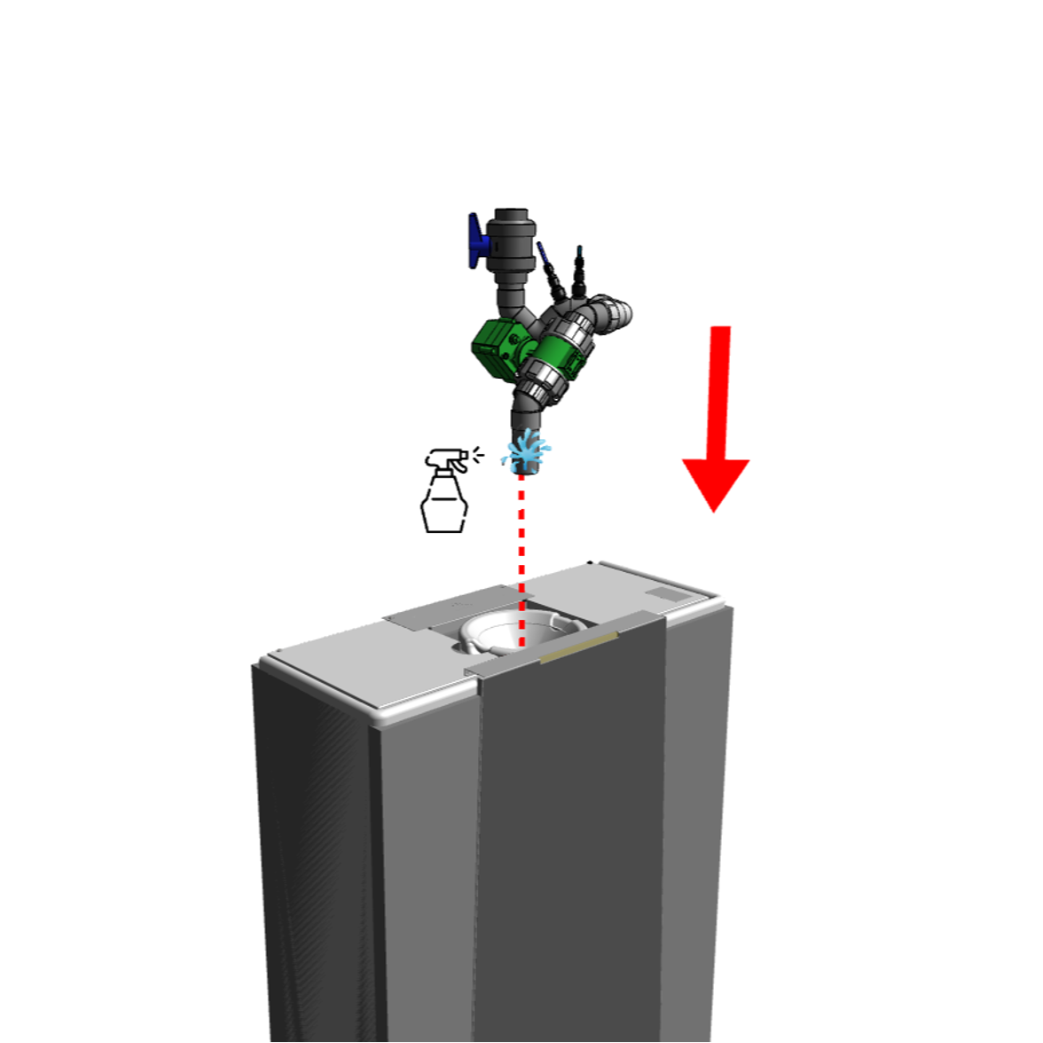
Step 1: remove top plates (use a T-20 bit/screwdriver)
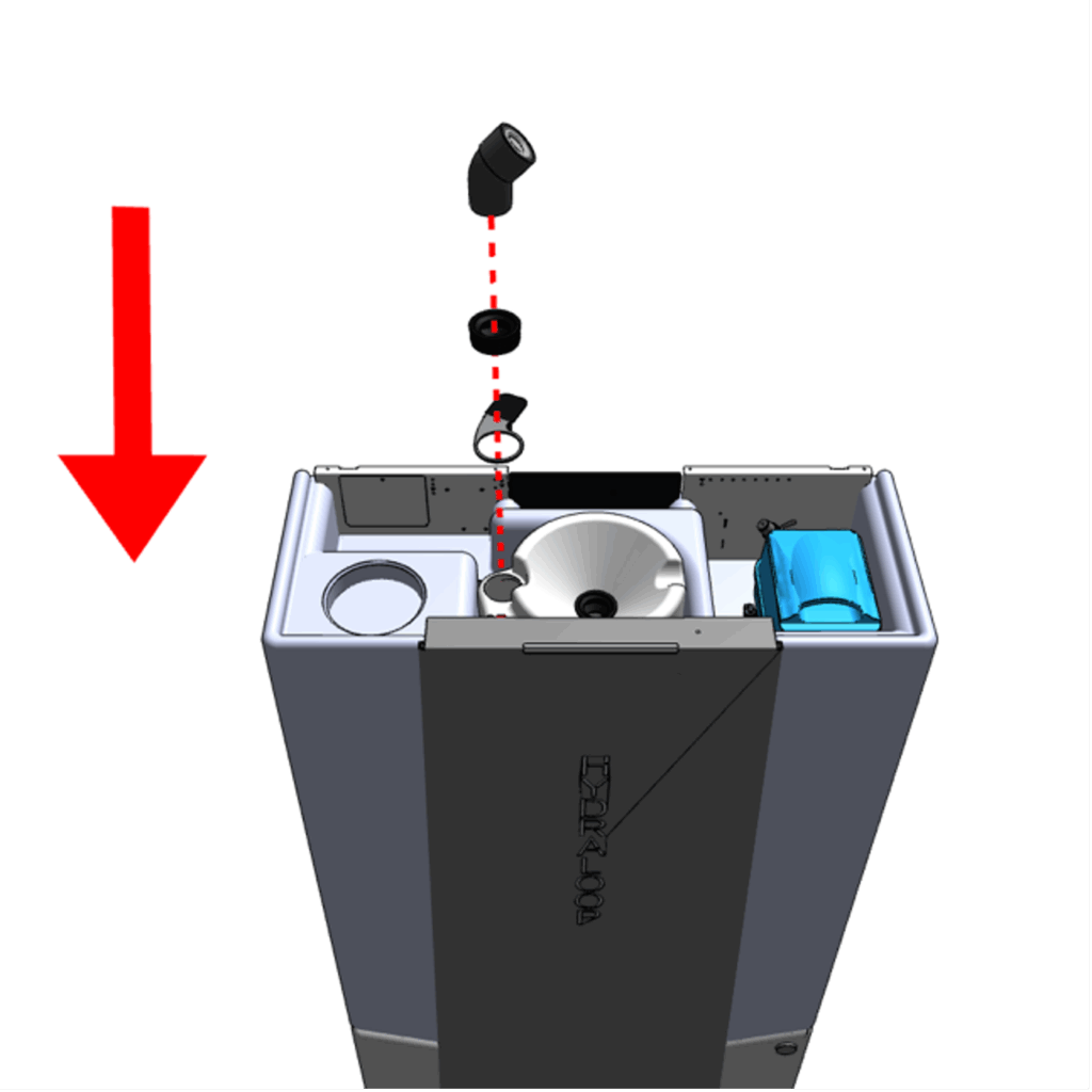
Step 2: install AAV with rubber gasket. Ensure aerator ring is placed underneath
Step 3: Replace base plates
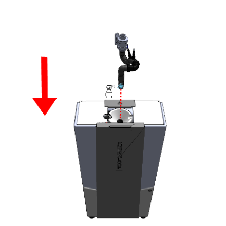
Step 4: Lubricate inlet and carefully push into T1
Step 5: Inlet is placed and be connected
Inlet manifold with inlet diverter #
The H300 comes with the standard inlet manifold shown below. The inlet manifold comes preassembled and needs to be placed on site.
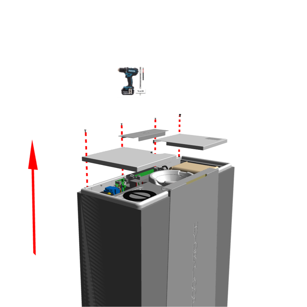
Step 1: remove top plates (use a T-20 bit/screwdriver)
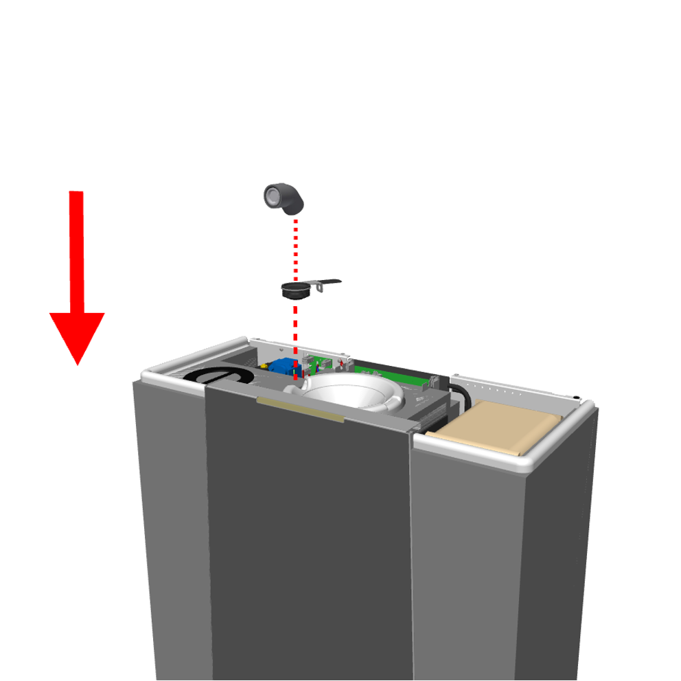
Step 2: install AAV with rubber gasket. Ensure aerator ring is placed underneath
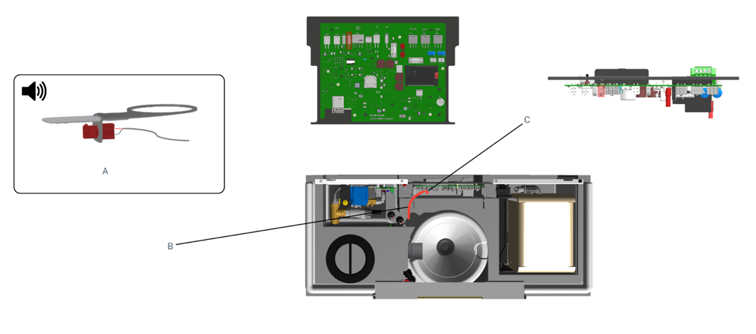
Step 3: Use the 300 mm cable to make a connection from the aerator ring (A) into the ECU (C). Routing the cable via (b). Use the X1-port on the ECU.
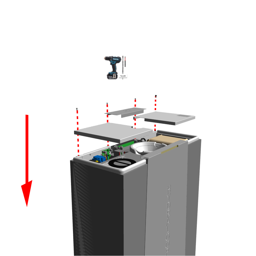
Step 4: Replace base plates
Step 5: Lubricate inlet and carefully push into T1
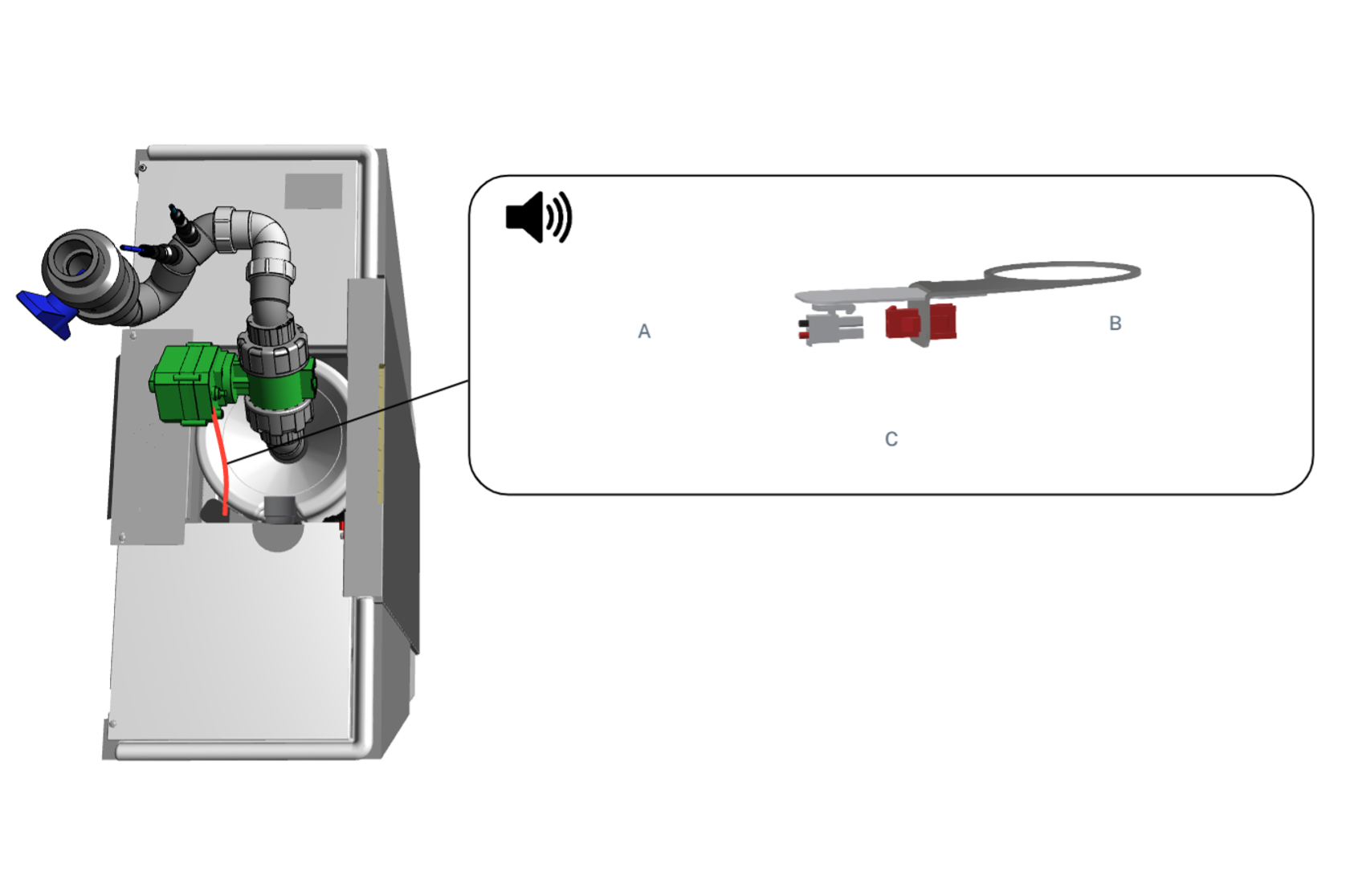
Step 6: Connect the cable from the Inlet Diverter Valve (IDV) into the Molex connection on the aerator ring (B).
Other installation requirements for inlet #
- Make sure to properly lubricate the black rubber rings on the AAV and inlet placement.
- Always use the supplied 40 mm manual shut off valve to the Hydraloop inlet manifold.
- Continue the grey water drain in the same diameter as an overflow pipe towards the sewage drain. The water line of the sewage drain needs to be at least 500 mm lower to prevent black water/sewage water to backflow into the Hydraloop.
- Connect the light (semi-transparent) and dark blue pressure tubes to inlet manifold. In downstream flow direction:
- Dark Blue
- Light Blue
- Resulting in the light blue pressure tube inserted closest to the Hydraloop inlet T1.
Overhead bypass to sewer #
When installing the grey water drain it is important not to restrict the internal diameter. Restricting the diameter downstream will negatively affect the functioning of the plumbing installation and the Hydraloop.
The Hydraloop inlet 40 mm. Create and overhead bypass according to the Recycle Ready Guide. Make sure the Y-junction that drops towards the Hydraloop is full bore, pointed down and in line with the flow to maximise the amount of water running into the Hydraloop.
After passing the Hydraloop inlet, connect the overhead bypass to the sewer connection. Make sure backflow of sewer water (i.e. black water) is made impossible. Backflow of sewer water will harm the functioning of the Hydraloop.
Recycled water outlets #
The Hydraloop device comes equipped with three standard outlet valves
- “WC” dedicated for feeding multiple toilets (no high flush toilets)
- “WM” dedicated for feeding one (1) washing machine
“AUX” auxiliary outlet (e.g. irrigation)
– Important –
Note: the “AUX” outlet will be activated after order as add-on. This outlet is not permanently pressurized and only used when surplus water is available.
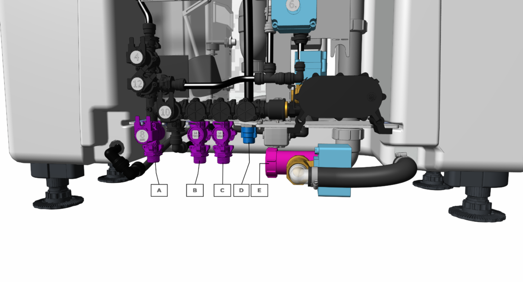
| Connection specifications Hydraloop H300 & H600 | |||
| Output connection | Size | Thread type | |
| A | “AUX” Auxiliary outlet (optional) | ½” | BSP male |
| B | “WC” Toilet outlet | ½” | BSP male |
| C | “WM” Washing machine outlet | ½” | BSP male |
| E | Drain to sewer outlet | 40 mm / 1 ½” | Union clamp |
| Input connection | Size | Thread type | |
| D | Backup water supply | ½” | BSP male |
(Optional) Greywater inlet via lift pump #
If the Hydraloop device is on the same or higher floor as the shower/bath or washing machine an external lift pump needs to be incorporated to pump greywater to the device. Ensure sufficient open-to-air ventilation from and to the lift pump and drainage fixtures. Always follow the lift pump manufacturers’ installation requirements.
Other lift pump considerations:
- Volume: Ensure the maximum volume of the lift pump holding tank is 50 litres. Larger volume tanks are known to negatively affect the grey water quality.
- Drain ventilation: Ensure open-to-air ventilation for the lift pump by installing a vent stack. Make sure the ventilation complies with local plumbing codes. If only a lift pump supplies the Hydraloop, the incoming gravity fed grey water drain into the Hydraloop also needs to be properly vented.
- Maximum flow: Choose a lift pump that has a maximum flow of 45 l/min or throttle the inlet flow.
Verification #
The Verification and activation of the Hydraloop device should only be carried out by approved installers who have prearranged their HDM login. This can only be done through messaging support@hydraloop.com. Once you have made your appointment you will receive authorization and your login.
- Verification and Activation: This step is conducted through the HDM by an approved and trained Installer with a pre-requested login to the HDM. Hydraloop Sales Engineers will be available for first time installers to assist and guide them through the process.
- Switch device from greywater bypass to the Hydraloop device
- Go through testing of all device systems via the HDM “verification”Select priority options connected to toilets, washing machine, auxiliary outlet, and lift pumps
- Activation of the H300 when all device systems have passed the validation steps. This will occur automatically once all HDM steps have been completed.
Testing for cross-connection using a dye test method #
– Important –
Testing for cross-connections shall be carried out directly after verification and before the greywater treatment system is in full operation.
Note: Experience has shown that biodegradable food colorants red and blue are suitably visible.
Control of the treated greywater distribution system: #
- Close the backup water supply prior to testing.
- Open all inline servicing valves of the recycled greywater lines.
- Dose dye into storage tank for treated greywater (T3) and start pressure pump for the distribution.
- Control all distribution points concerning the appearance of colored water:
- Outlets for non-potable water showing colored water: PASS;
- Outlets for potable water with colored or non-colored outflow: FAIL;
- prohibited cross-connection between potable and non-potable water distribution system.
Control of cross-connections in the greywater harvesting system: #
- Dosing of dye into all non-greywater harvesting points (e.g. toilet, kitchen sink)
- No coloured water in the greywater treatment system: PASS;
- Coloured water in the greywater treatment system: FAIL
- wrongly connected collection points.
After testing the whole system shall be thoroughly flushed to remove all residual traces of colorant before it is commissioned and put into operation.
Startup time #
The Hydraloop device requires a minimum of 21 days (3 weeks) and 20 showers to develop the biological treatment process in the T2 tank and become fully operational. During this startup period the system will be in backup water mode. After this start-up period of 21 days (3 weeks) and 20 showers, the Hydraloop device will automatically switch over to deliver reusable water to the toilets, washing machine and/or auxiliary outlet.
Backup water and backflow prevention #
In the startup period and in case there is not enough reusable water available, the device will automatically switch to backup water. The device is connected to its backup water supply via a certified safe air gap to protect the backup water connection against backflow or cross contamination. Additionally, a non-return valve is mounted on the point of incoming backup water.
NOTE: If using rainwater as a backup water supply, pretreatment must be applied prior to entering the Hydraloop device. This treatment must be done according to EN 16941-1 or similar. Pretreatment should include at least a 5-micron filter and carbon filtration, UV disinfection, expansion vessel and a pressure regulator (depending on the booster pump). The incoming flowrate should be at least 12 lpm | 3.2 gpm, 1.5-3 bar | 21.75 – 43.5 psi.
Accessing the HDM #
- Open hdm.hydraloop.com in your browser
- Sign in with your Username and Password as supplied via email from your Hydraloop Sales Engineer
- Two-factor authentication is required, enable it to gain complete access
- Install the APP of your operating system choice
- Scan QR code
- Enter verification code
- Change your password
- Save Changes (Save icon in top right-hand corner)
Once logged into HDM you will be instructed to scan the barcode on the top of the Hydraloop device. Scanning the barcode will open your device up onto the HDM and the verification process will begin. You will be given instructions on how to proceed to the next steps.
The Hydraloop APP needs to be downloaded on both the Installers and device owners smartphone.
If you need assistance, please call your Hydraloop dealer or contact Hydraloop Sales Engineer via email support@hydraloop.com
Water supply bypass facility #
During periods of unscheduled maintenance, service, or power failure it might be possible that supply of reusable or backup water is temporarily not available. To overcome this a bypass can be installed. The bypass setup must comply with the applicable regulations of the country, state, or municipality.
System malfunction #
Your Hydraloop device is very reliable, with all critical components being monitored continuously by the Hydraloop server through your Wi-Fi internet connection. In the unlikely event a component failure, the Hydraloop system will automatically switch to backup water and stop distribution of reusable water as a precaution.
Explanation visual alarm lights and audible alarm #
VISUAL STATUS INDICATIONS #
White light: A white light indicates that there is a sufficient volume of reusable water for all uses.
Blue light: A blue light indicates that there is currently no reusable water available and backup water is being used for all purposes.
Blue white alternate light: A blue-white alternating light indicates that there is reusable water in the storage tank, but not enough for a full washing machine cycle.
Green light: A green light indicates that the Hydraloop device is in automatic cleaning mode.
Purple light: A purple light indicates that the Hydraloop device is detecting that the washing machine is in operation.
Orange light: An orange light indicates that your Hydraloop device is currently not treating greywater and has automatically switched over to backup water.
Since your device is monitored 24/7, your Hydraloop installer knows about this. If the status light does not change after 24 hours, please contact Hydraloop support in your Hydraloop app.
Red light: A red light on the LED panel can indicate two things.
1. The Hydraloop device detects an issue with your toilets or washing machine.
2. There is an issue with the Hydraloop device, and no water can be distributed to the toilets and washing machines. In the event of a red light, please open your Hydraloop app and contact Hydraloop directly.
AUDIBLE STATUS INDICATIONS #
High water level: Buzzer alarm: 2 beeps every minute, visual alarm: 2 pulses every minute
Air pump: Buzzer alarm: 3 beeps every minute, visual alarm: 3 pulses every minute
UV lamp: Buzzer alarm: 4 beeps every minute, visual alarm: 4 pulses every minute
Water storage tank re-disinfection circulation: Buzzer alarm 5 beeps every minute, visual alarm: 5 pulses every minute
Water distribution pump: Buzzer alarm: 6 beeps every minute, visual alarm: 6 pulses every minute
If you need assistance, please call your Hydraloop installer or contact Hydraloop directly via support@hydraloop.com or the Hydraloop app.
Warranty #
For detailed information on the warranty coverage, please review your warranty certificate. It is essential to ensure that all your personal information is accurately entered into your Hydraloop APP.
Under this Factory Warranty (“Warranty”), Hydraloop guarantees to the original purchaser of the Hydraloop device (referred to as the “Product”) as outlined in Part 1 of the Warranty Policy under “Customer,” that the Product will be free from material Defects for a period of two (2) years from the date of the original purchase invoice from Hydraloop or one of its authorized Partners, unless local jurisdiction mandates a longer term. In these warranty terms, a “Defect” refers to a manufacturing or design flaw that significantly affects the Product’s use, solely attributable to Hydraloop, and not detectable at the time of Product delivery.
To assist Hydraloop device owners in entering their information, contact details, and physical address into the warranty section on the Hydraloop APP, the Hydraloop installer will provide support.
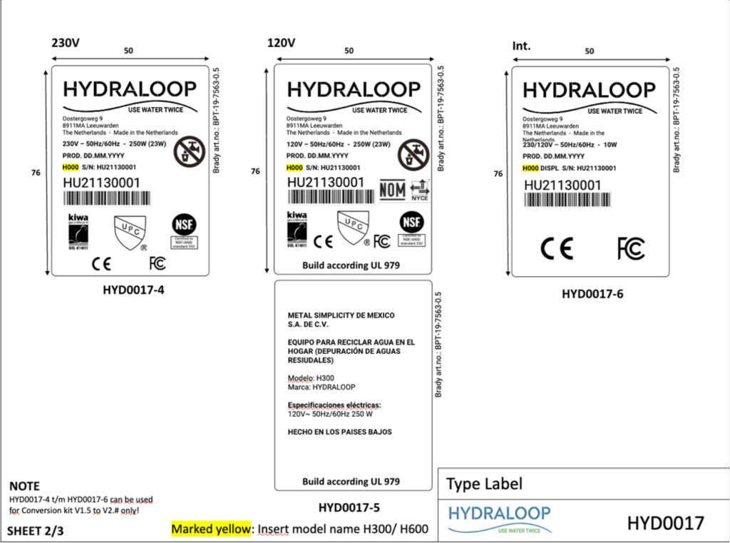
Data plate/Service Label #
The Hydraloop device has a permanent data plate attached to the top and behind the front plate of the device that should look like the example below.
Glossary of terms #
Auxiliary Outlet
A non-pressurized valve that distributes reusable water for garden irrigation or pool top-up, depending on the region. Water is only available when present in the holding tank (T3) or as controlled by the HDM.
Backup Water
The primary water source for a building, such as mains tap water, municipal water, treated well water, or treated rainwater.
Wastewater
Highly contaminated sewer water containing pathogens, originating from toilets, bidets, hand showers, floor drains, dishwashers, and kitchen sinks.
Greywater
Lightly contaminated domestic water from baths, showers, and washing machines.
Hydraloop App
A smart app for monitoring Hydraloop device performance, offering water-saving tips, and sending notifications. It alerts users when the device is ready to distribute reusable water (after 21 days and 20 showers/baths).
Hydraloop Device Manager (HDM)
An online platform for installing, testing, verifying, and managing Hydraloop devices. It enables monitoring, maintenance, troubleshooting, and ticket generation. Login credentials, provided by Hydraloop, are required before installation.
Inlet Diverter
An optional valve that allows greywater intake from sources other than showers/baths, required when adding washing machine water.
Recycle Ready Guide
A guide for owners, plumbers, and contractors on preparing a building’s plumbing system for greywater recycling.
Recycle Ready Checklist
A required checklist, signed by the responsible party to prepare the buildings’ plumbing, ensuring the system is ready before installation can be scheduled.
Reusable Water
Recycled greywater used for toilet flushing, washing machine, or outdoor applications.
Start-up Time
The Hydraloop device needs at least 21 days and 20 showers to establish its biological treatment process. If fewer than 20 showers occur within 21 days, the start-up period extends.
Open to Air Ventilation
A ventilation system preventing siphoning in the greywater line. Ensure proper two-way ventilation for both greywater input and sewage output, with the greywater vent terminating outside the building.
This document and its contents exclusively belong to Hydraloop Systems B.V. and must not be reproduced, whether in part or in whole, without the prior written consent of Hydraloop Systems B.V. Hydraloop retains the right to modify the specifications provided in this document.
Hydraloop products are safeguarded by existing patents and patents pending. The Hydraloop brand name is a registered trademark.